Palo Alto Networks IPsec Configuration
This section describes how to configure two IPSec VPN tunnels on a PA-200 firewall running version 9.1.x. Refer to Palo Alto Networks documentation for additional information about the web interface.
IPSec Connectivity Guide for Palo Alto Networks Firewall
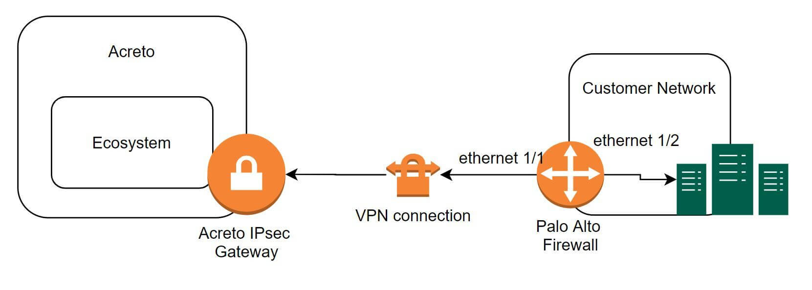
The ethernet1/2 interface is connected to the internal corporate network. This interface will act as a gateway to the internal corporate network. The ethernet1/1 interface is the external interface. The internal network configuration will be in a trust security zone, and the external network interface configuration will be in an untrust security zone. Also, ensure that both interfaces use the same Virtual Router service.
To configure the IPSec VPN tunnels on PA-200, complete the following tasks:
Task 1: Create a New Virtual Router
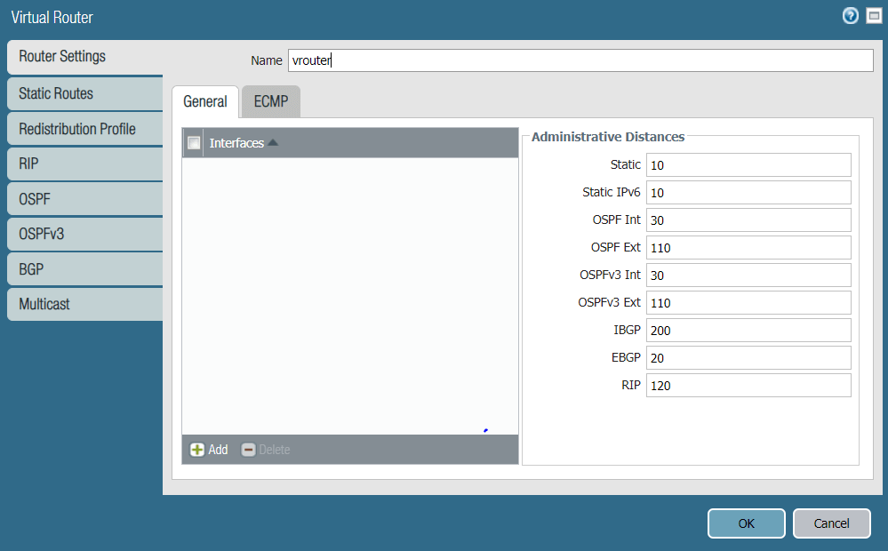
For this task, you will create a new Virtual Router. To configure the new Virtual Router:
- In the Palo Alto Networks web interface, go to Network → Virtual Routers.
- Click Add to add a new Virtual Router.
- Enter the Virtual Router name, in this case vrouter.
- Click OK to save the vRouter configurations.
Show image
Task 2: Create New Zones
It is recommended to use separate zones to setup IPsec tunnels with PAN.
To configure trust and untrust zones, execute the following commands:
- In the Palo Alto Networks web interface, go to Network → Zones.
- Click Add to create a new zone.
- Enter the trust zone name, in this case trust. Choose zone type Layer3.
Show image
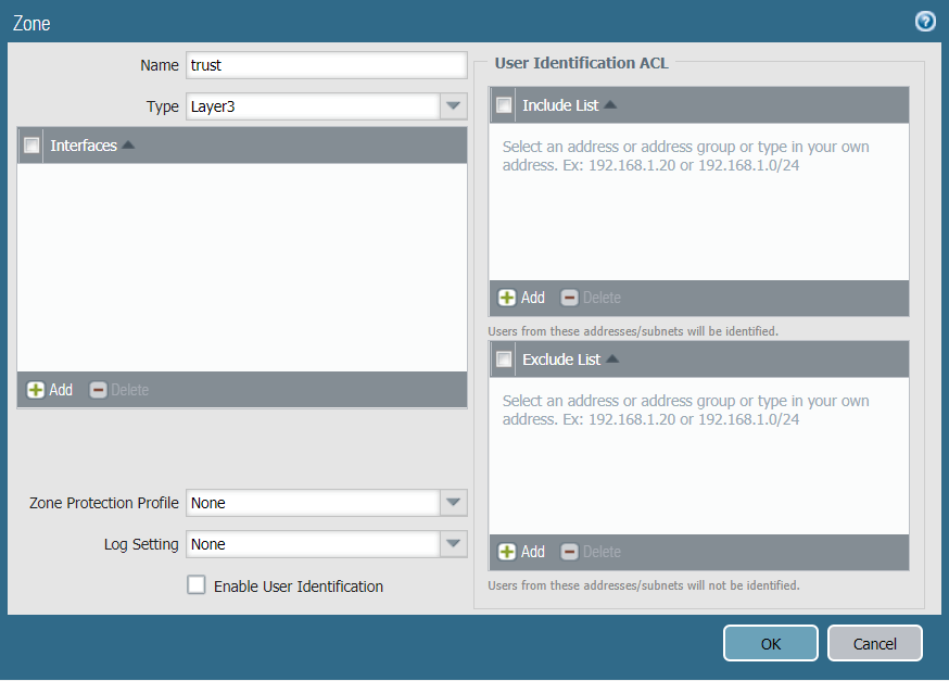
- Click OK to save the zone.
- Click Add to create a new zone.
- Enter the untrust zone name, in this case untrust. Choose zone type Layer3.
Show image
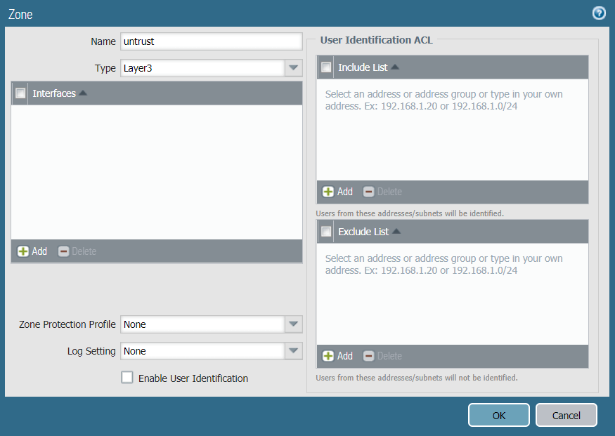
- Click OK to save the zone.
Task 3: Configuring the External Ethernet Interface
Configure the external network interface on PAN to be an untrust zone.
- In the Palo Alto Networks web interface, go to Network -> Interfaces
- Navigate to the Ethernet tab and click on Ethernet 1/1
- Set the Interface Type to Layer3
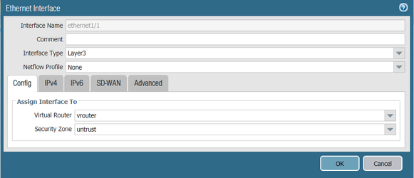
- Configure the ethernet 1/1, assign it to an untrust zone and connect to vrouter Virtual Router
Show image
- Configure the IP address on the external network, in this example 10.1.203.96/24
Show image
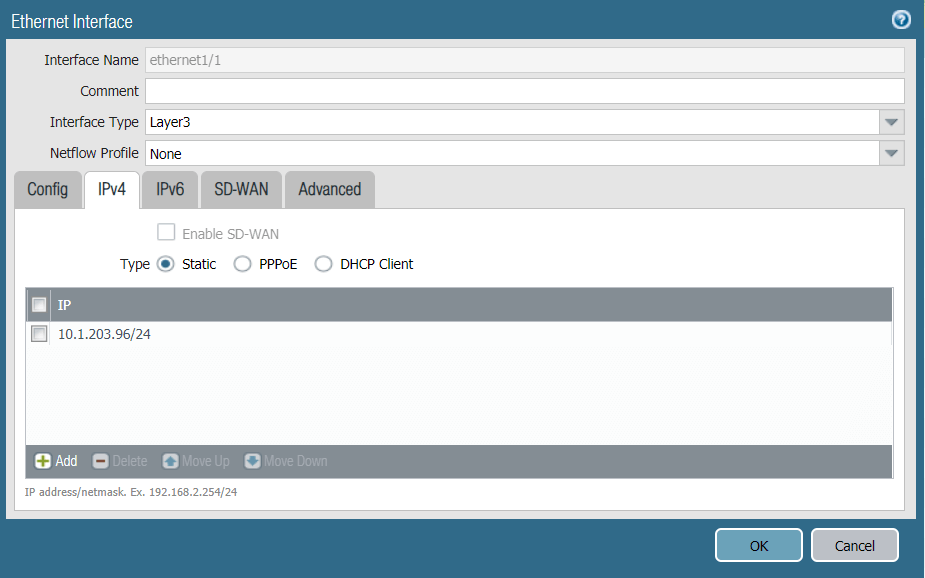
- Click OK to save the configurations
Task 4: Configuring the Internal Ethernet Interface
Configure the internal network interface on PAN to be a trust zone.
- In the Palo Alto Networks web interface, go to Network -> Interfaces.
- Navigate to the Ethernet tab and click on Ethernet 1/2.
- Set the Interface Type to Layer3.
- Configure the ethernet 1/2, assign it to a trust zone and connect to vrouter Virtual Router.
Show image

- Configure the IP address on the internal interface, in this case 10.1.201.96/24.
Show image
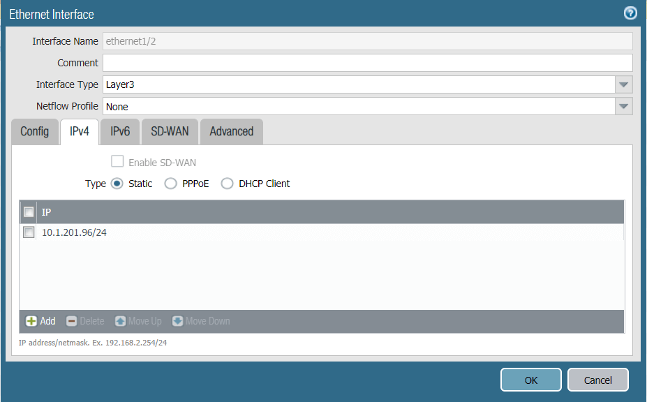
- Click OK to save the configurations.
Task 5: Configuring the Tunnel Interfaces
Configure the tunnel interface on the external interface (ethernet1/1). Ensure the tunnel is configured in the untrust security zone. In this example, the tunnel interface is named tunnel.1 with a source IP address 10.1.203.93.
To configure the primary tunnel interface:
- In the Palo Alto Networks web interface, go to Network -> Interfaces.
- Click the Tunnel tab.
- Click Add to create a new tunnel interface.
- In the Tunnel Interface window, complete the following:
Show image
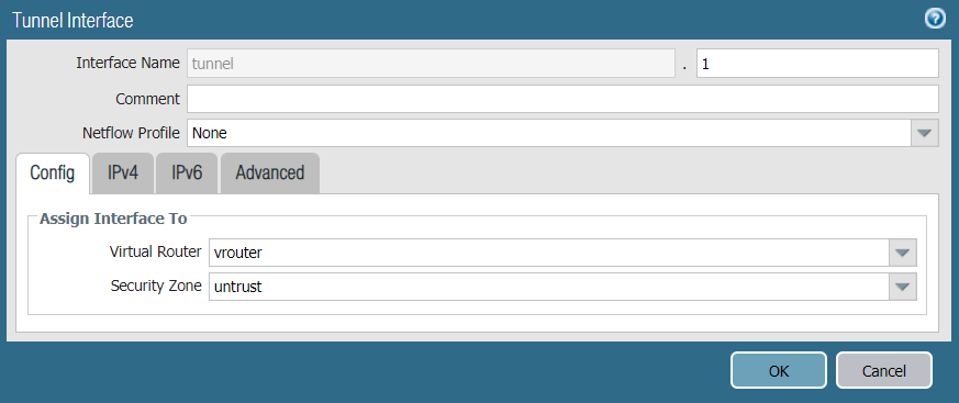
- Interface Name: Enter a name for the tunnel interface, such as tunnel.1.
- Netflow Profile: Choose the appropriate NetFlow profile. In this example, it’s None.
- Comment: Enter additional notes or information (optional).
- Assign Interface To:
- Virtual Router: Choose vrouter.
- Security Zone: Choose untrust.
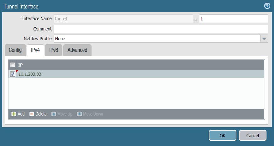
- Under the IPv4 tab, assign IP address 10.1.203.93 to the tunnel.1 interface.
Show image
- Click OK to save the tunnel interface.
- Click *Commit to apply the configurations.
Task 6: Creating the IKE Crypto Profile
Create an IKE crypto profile that specifies the security settings for the IKE phase 1 negotiations.
To create an IKE crypto profile:
- In the Palo Alto Networks web interface, go to Network.
- Expand Network Profiles.
- Select IKE Crypto.
- Click Add to create an IKE crypto profile.
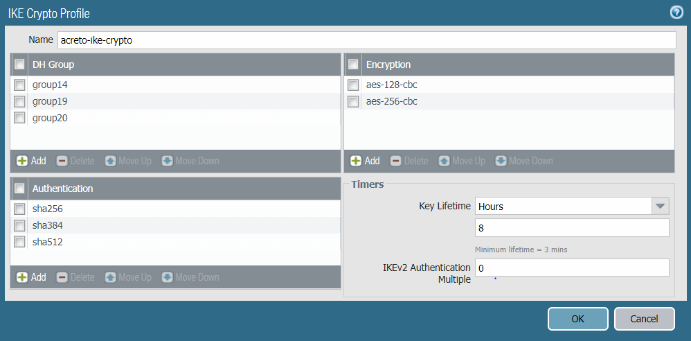
- In the IKE Crypto Profile window, complete the following:
- Name: Enter a name for the IKE crypto profile. In this case: acreto-ike-crypto.
- DH Group: Click Add and choose group14, group19, group20.
- Encryption: Click Add and choose aes-128-cbc aes-256-cbc.
- Authentication: Click Add and choose sha256, sha384, sha512.
- Lifetime: Set it to 8 hours.
Show image
- Click OK to save configurations.
Task 7: Creating the IKE Gateway
Create IKE gateways using the Acreto Gateway IP address. In this case: 104.193.146.132.
To create the primary IKE gateway:
- In the Palo Alto Networks web interface, go to Network.
- Expand Network Profiles.
- Click IKE Gateways.
- Click Add.
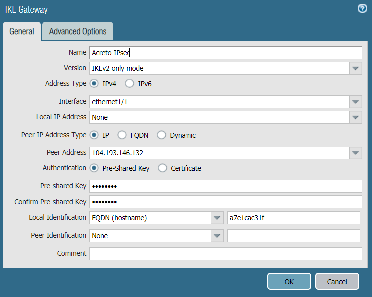
- In the IKE Gateway window, complete the following:
- Name: Enter a name for the IKE gateway, such as Acreto-IPsec.
- Version: Select IKEv2 only mode.
- Interface: Choose the external interface ethernet 1/1.
- Local IP Address: Choose None.
- Peer IP Type: Choose Static.
- Peer IP Address: Enter the Acreto Gateway address for the primary gateway. In this case, it's 104.193.146.132.
- Pre-shared Key: Enter the pre-shared key you generated in the Acreto web Portal.
- Confirm Pre-shared Key: Reenter the pre-shared key.
- Local Identification: Enter the Peer ID from the Acreto Web Portal.
- Peer Identification: Choose None.
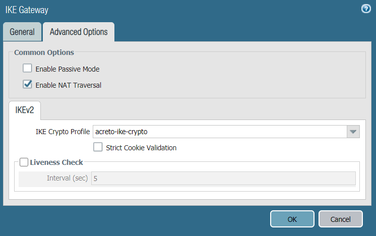
- Show Advanced Phase 1 Options: Select to show the following options.
- IKE Crypto Profile: Choose the IKE crypto profile you created in the previous step. In this case, it's acreto-ike-crypto.
- Enable Passive Mode: Deselect.
- Enable NAT Traversal: Select.
- Liveness Check: Deselect.
- Below are reference snapshots of the IKE gateway configurations.
Show image
Show image
- Click OK to save configurations.
Note: To view the Acreto Web Portal information, complete the following steps:
- Log in to https://wedge.acreto.net/.
- Click on the Ecosystem you want to connect to.
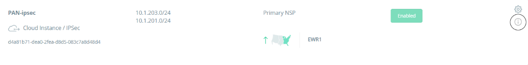
- Navigate to Elements → Objects → Gateways.
- Navigate to the gateway you want to connect to and click the Information sign on the right.
Show image
- A new window will appear. Click on “VPN Parameters” to expand the details:
Show image
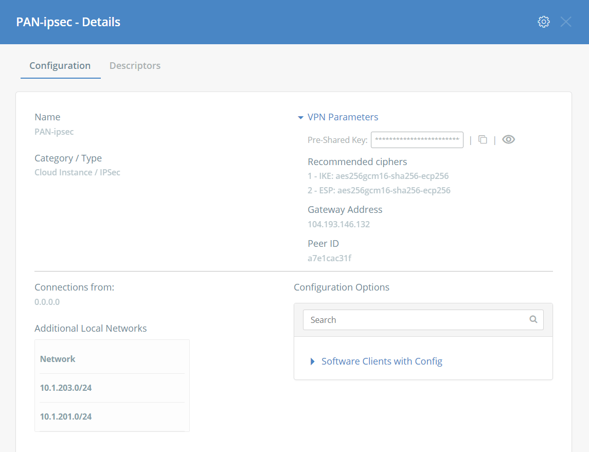
- From here you can view the Pre-Shared Key, Gateway Address and Peer ID.
- These parameters will be used for Task #7.
Task 8: Creating the IPSec Crypto Profile
Create an IPSec crypto profile that specifies the security parameters for the IKE phase 2 negotiations.
To create an IPSec crypto profile:
- In the Palo Alto Networks web interface, go to Network.
- Expand Network Profiles.
- Click IPSec Crypto.
- Click Add to create a IPSec crypto profile.
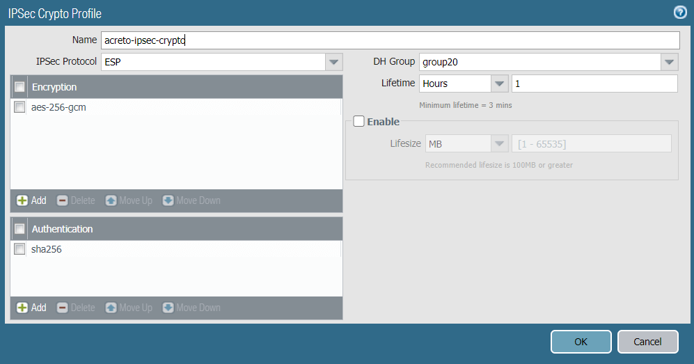
- In the IPSec Crypto Profile window, complete the following:
- Name: Enter a name for the IPSec crypto profile, such as acreto-ipsec-crypto.
- IPSec Protocol: Ensure ESP is chosen.
- Encryption: Click Add and choose aes-256-gcm to encrypt the traffic.
- Authentication: Click Add and choose sha256.
- DH Group: Ensure group20 is chosen.
- Lifetime: Set it to 1 Hour.
- Lifesize: Set the lifesize according to your incoming traffic volume (optional).
- Reference snapshot of IPsec crypto profile.
Show image
- Click OK to save configurations.
Task 9: Creating the IPSec VPN Tunnels
Configure the IPSec VPN Tunnel using the Acreto Gateway Address. In this case, 104.193.146.132
To create the IPSec VPN tunnel:
- In the Palo Alto Networks web interface, go to Network -> IPSec Tunnels.
- Click Add to create a new IPSec tunnel.
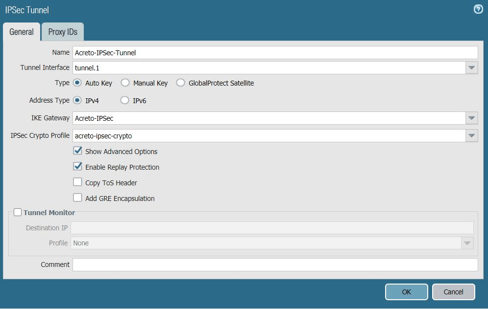
- In the IPSec Tunnel window under the General tab, complete the
following:
- Name: Enter a name for the tunnel, such as Acreto-IPsec-Tunnel.
- Tunnel Interface: Choose the tunnel interface you created in Configuring the Tunnel Interfaces. In this case, it's tunnel.1.
- Type: Ensure Auto Key is chosen.
- IKE Gateway: Choose the primary IKE gateway you created in Creating the IKE Gateway section. In this case, it's Acreto-IPsec.
- IPSec Crypto Profile: Choose the IPSec crypto profile you created in Creating the IPSec Crypto Profile. In this case, it's acreto-ipsec-crypto.
- Show Advanced Options: Select to show the following options.
- Enable Replay Protection: Select.
- Copy TOS Header: Deselect.
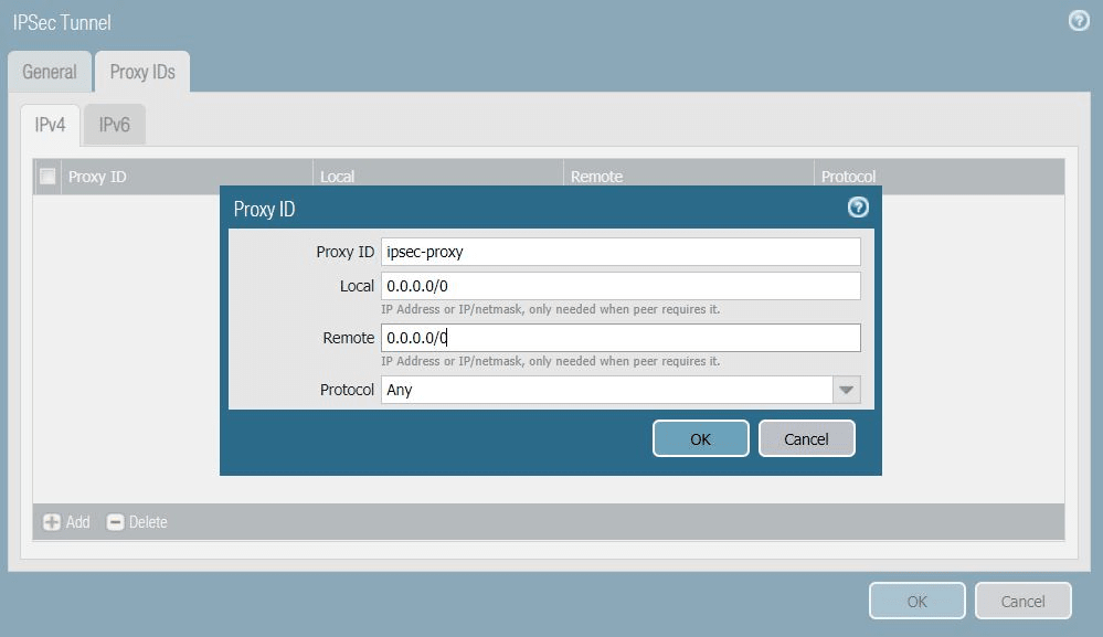
- In the Proxy IDs tab, click Add and complete the following:
- Proxy ID: Enter a name for the proxy.
- Local: Enter the local IP address 0.0.0.0/0.
- Remote: Enter the remote IP address 0.0.0.0/0.
- Protocol: Ensure Any is chosen.
- Click OK to save the proxy ID.
- Click OK again to save the IPSec tunnel configurations.
- Reference configuration for the IPSec Tunnel is described in the snapshots below:
Show image
Show image
- Click Commit to apply configurations on PAN.
Task 10: Defining the Policy-Based Forwarding Rule
Defining two policy-based forwarding rules to route the traffic from the Palo Alto Network appliance into the tunnel.
To define the primary policy-based forwarding rule:
- In the Palo Alto Networks web interface, go to Policies -> Policy-Based Forwarding.
- Click Add to create a new rule.
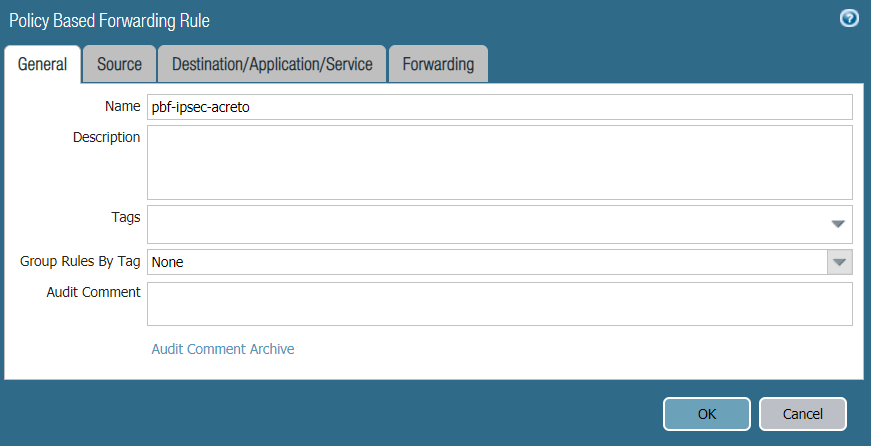
- In the General tab, complete the following:
- Name: Enter a name for the policy, such as pbf-ipsec-acreto.
- Description: Enter a description (optional).
- Tags: Choose a tag (optional).
- Reference configurations are described in the image below:
Show image
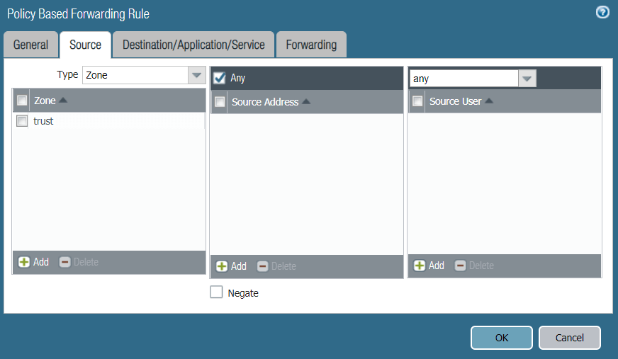
- In the Source tab, choose Type Zone. Under Zone, click Add and choose trust. Reference configurations of the Source tab are below:
Show image
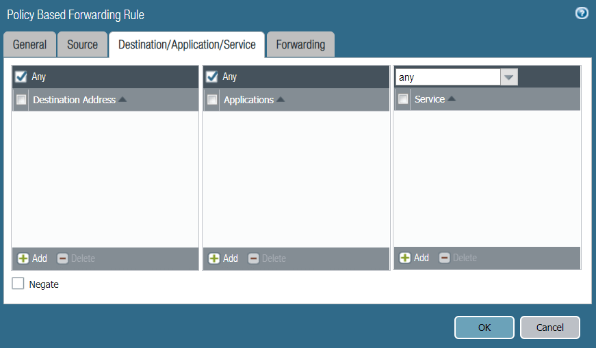
- In the Destination/Application/Service tab, complete the following:
- Destination Address: Ensure Any is selected.
- Applications: Ensure Any is selected.
- Service: Ensure Any is selected.
- Reference configurations of this tab are described in the image below:
Show image
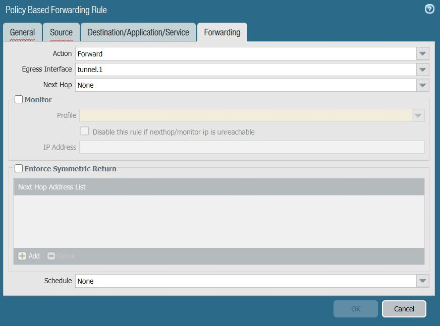
- In the Forwarding tab, complete the following:
- Action: Choose Forward.
- Egress Interface: Choose the primary tunnel interface you created in task 5. Configuring the Tunnel Interfaces. In this case, it's tunnel.1.
- Next Hop: Leave this field blank.
- Monitor: Deselect.
- Enforce Symmetric Return: Deselect.
- Schedule: Choose None.
- Reference configurations for this tab are described in the image below:
Show image
- Click OK to save the configurations.
- Commit the changes in PAN.
Task 11: IPSec Tunnel Status
Once completing the above step, the IPsec tunnel will be established between PAN and the Acreto IPsec Gateway. To check the status of the tunnel, navigate to Network → IPSec Tunnels and view the tunnel status. A green color status signifies that the tunnel is established correctly.

Task 12: Configure Routing on PAN
To validate the network traffic going from PAN to the Acreto IPsec gateway, routes must be configured in the virtual router in PAN. Execute the following steps to configure the routes:
- In the Palo Alto Networks web interface, go to Networks -> Virtual Routers.
- Click on the router that was created in the previous task, in this case vrouter.
- From the left panel, select Static Routes.
- Click Add to add a new route.
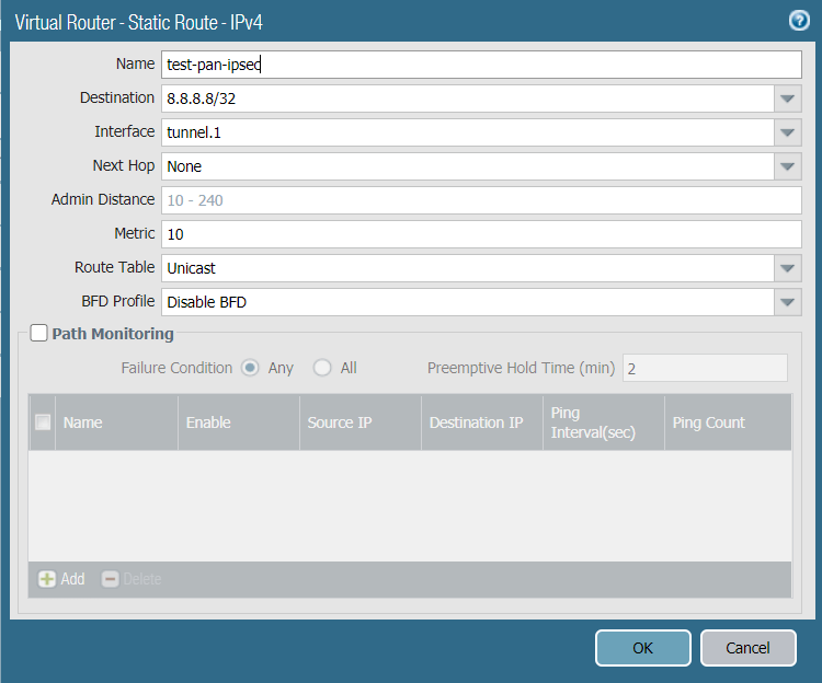
- Configure the route fields according to the details below:
- Name: test-ipsec-pan.
- Destination: 8.8.8.8/32.
- Interface: tunnel.1.
- Next Hop: None.
- Admin Distance:
- Metric: 10.
- Route Table: Unicast.
- BFD Profile: Disable BFD.
- Path Monitoring: Deselect.
- Reference configurations of this route are described in the image below:
Show image
- Click OK to save the configurations.
- Click Commit to apply the configurations.
Task 13: Verifying the Connectivity
In this section, the connectivity between PAN and Acreto gateway will be verified.
-
SSH to the PAN device.
-
Run the following command below:
ping source <tunnel.1 IP address> host 8.8.8.8 -
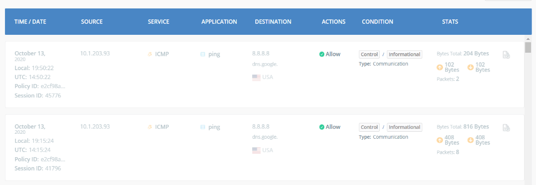
The ping should work with a sample output like below:
-
You should be able to see these traffic logs in the Acreto Reports dashboard. Navigate to the Ecosystem and from the left panel, select Reports. Below is a sample of the reports from the Acreto Web Portal: