Subsections of Acreto Connect Client - administrator guide
Connect the Thing with Acreto Connect Client
Before You Start
Overview
In this article, you’ll learn how to create and connect Thing to the Acreto ecosystem.
This Use Case allows you to securely connect client (PC, laptop, smartphone) to the office ecosystem.
- Configure the Thing
- Install Acreto Connect Client
Prerequisites
To connect your Thing to the Ecosystem, you will need:
- Existing Acrereto Ecosystem, if you don’t have one learn how to create it.
- Access to Acreto Wedge.
- A device that you want to connect to the Ecosystem.
How To
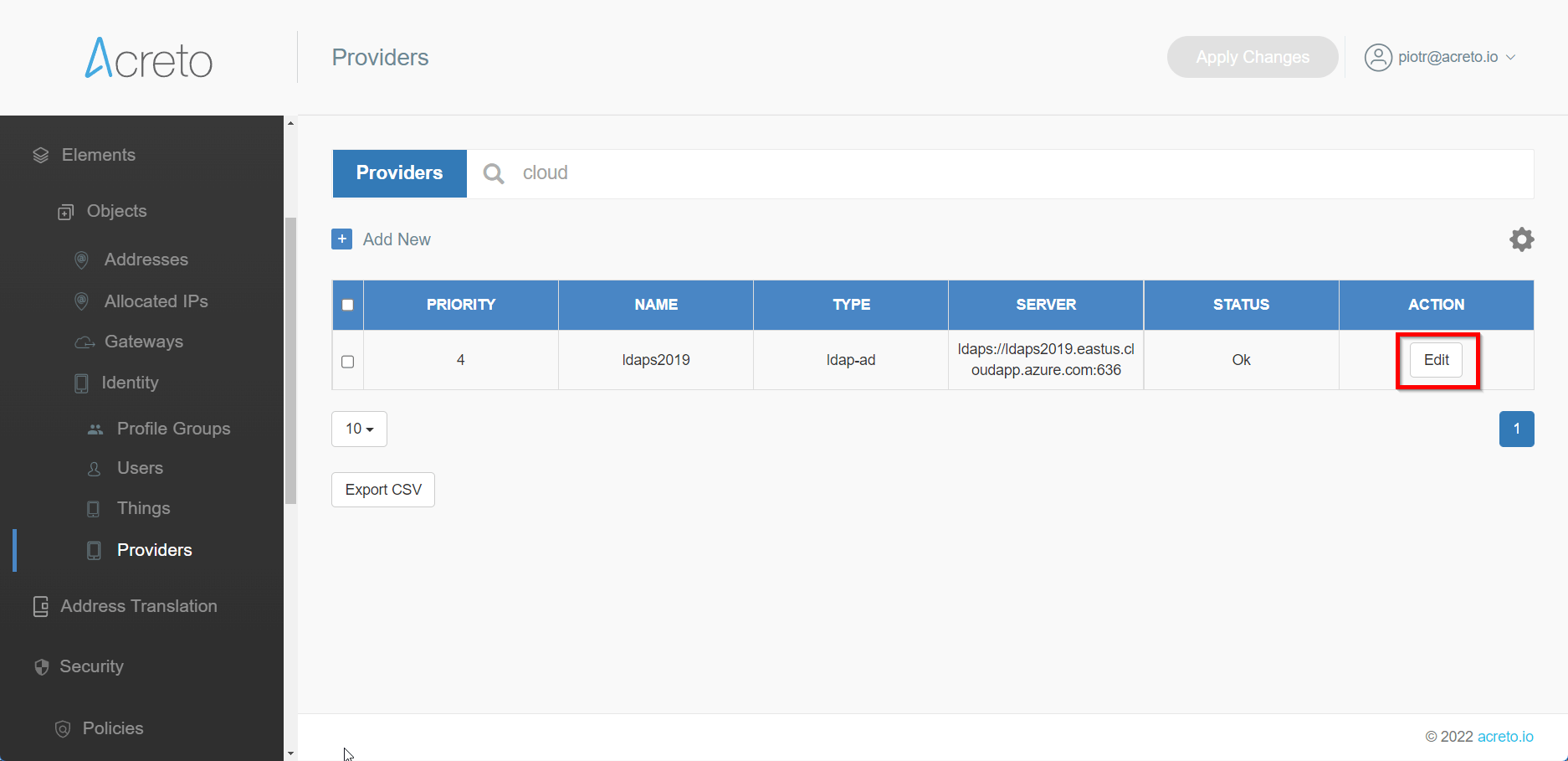
- Log in to the Wedge
- Choose your Ecosystem.
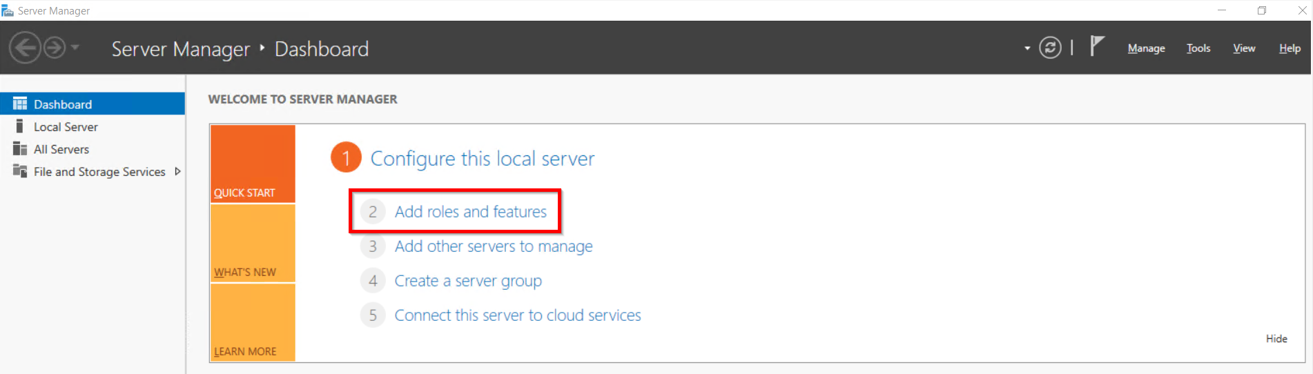
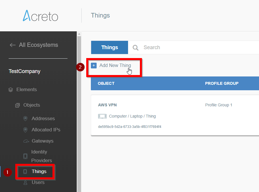
- From the left menu choose Objects > Things (1) and click on this option.
- In the Things panel click on the + Add New Thing button (2)
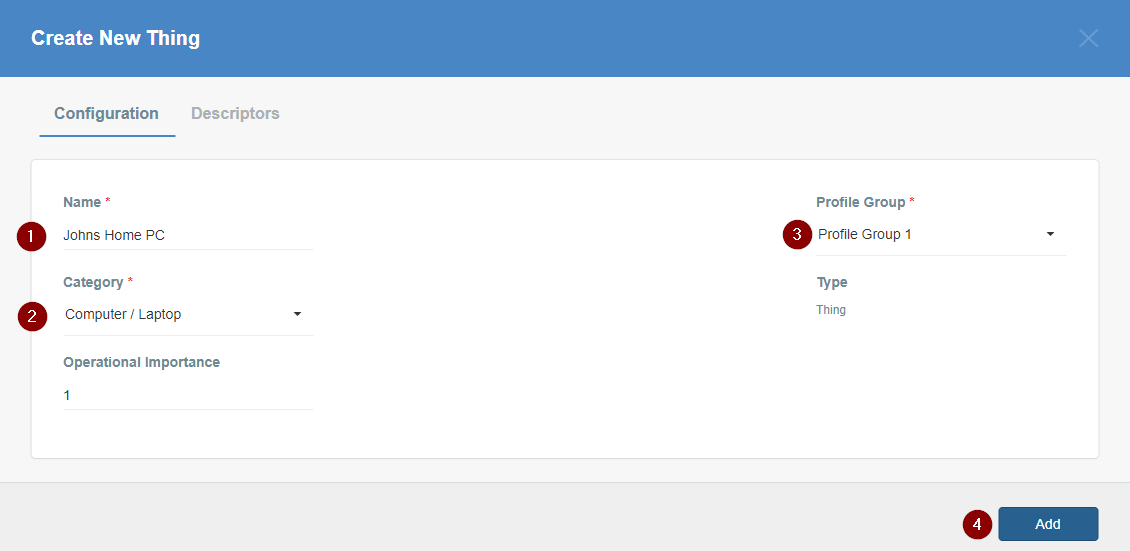
- Fill the form:
- Input the descriptive name of the device.
- Choose the category of the device.
- Choose the Profile Group for the device if you have more than one group. Otherwise, leave the default value.
- Save the form to add the Thing.
- The newly created Thing is now available on the list.
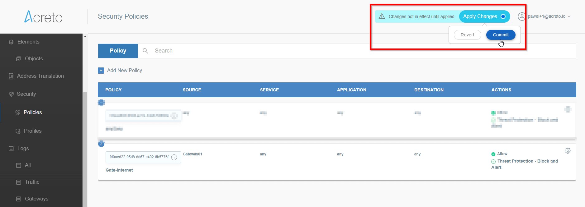
- Click on the Apply changes button on the top of the screen to commit a new thing to the Ecosystem.
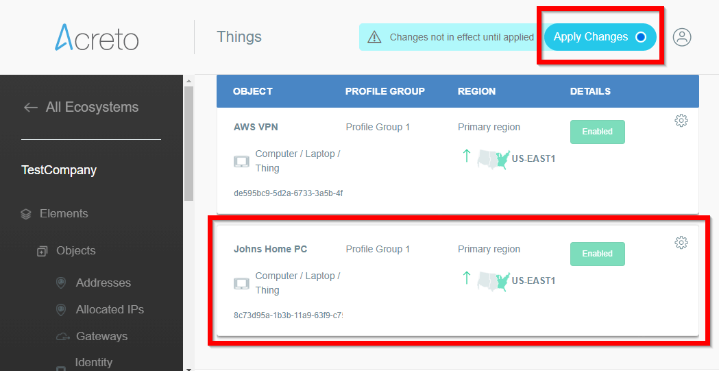
- Wait for the changes to be applied
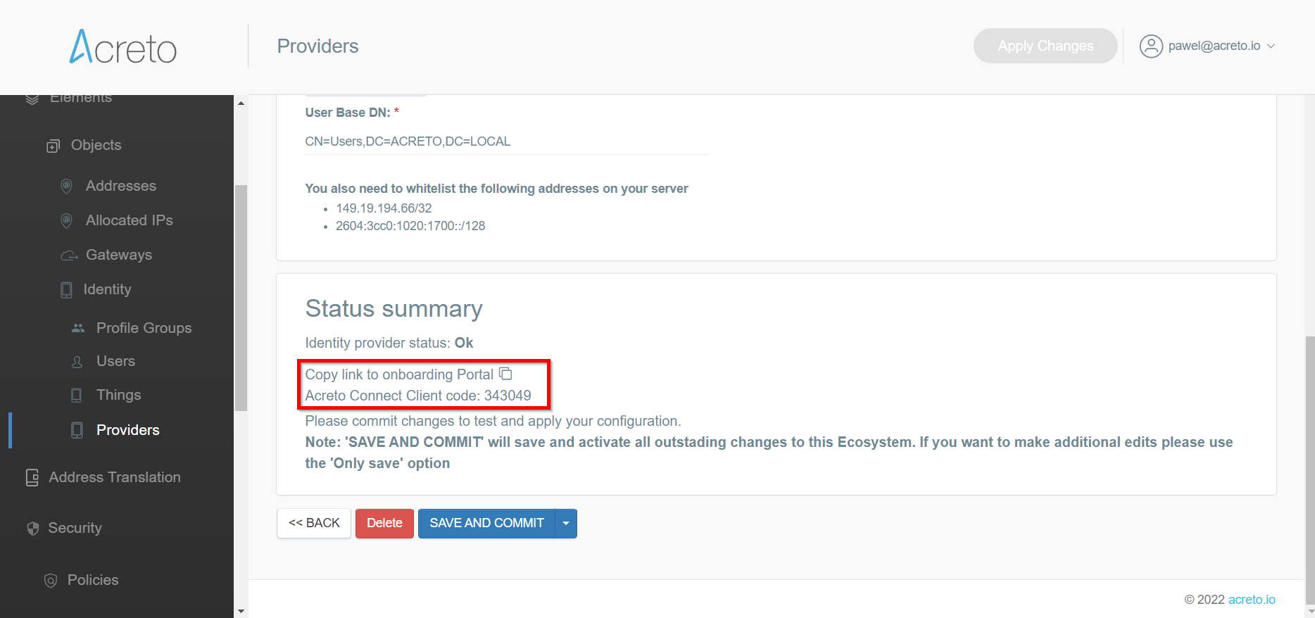
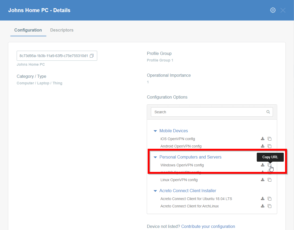
- Click on the name of created Thing to see its details.
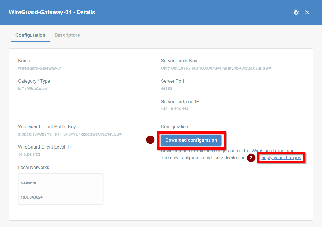
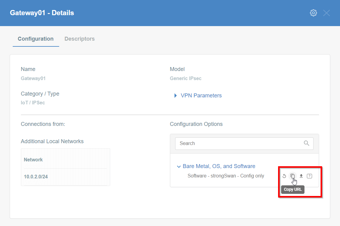
- On the right part of the details screen you may see Configuration Options - find the right configuration file for your device and copy the link by clicking on the icon.
Install Acreto Connect Client
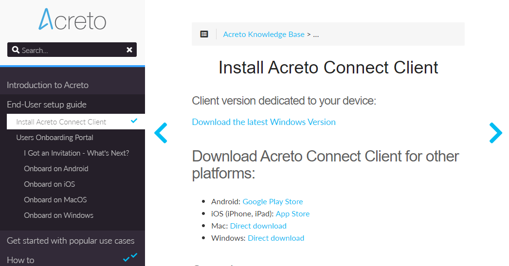
At first, you need to download and install Acreto Connect Client - a small application that allows you to connect to the Acreto ecosystem.
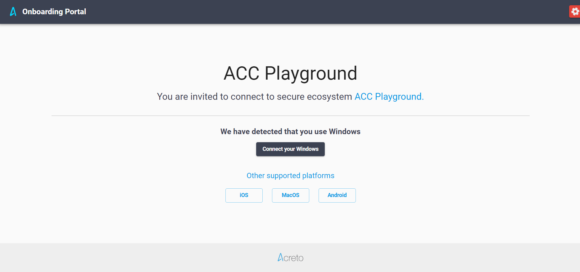
- Open kb.acreto.net/client on the device which you want to connect to the Ecosystem.
- Download the ACC version for your operating system - this page tries to recognize the type of your device and allows you to download the dedicated version.
- When the installation file is downloaded, install the Acreto Connect Client.
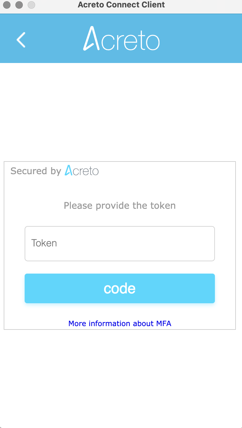
- Run Acreto Connect Client - the interface of the application is the same on all platforms. You should get a screen similar to this shown below:
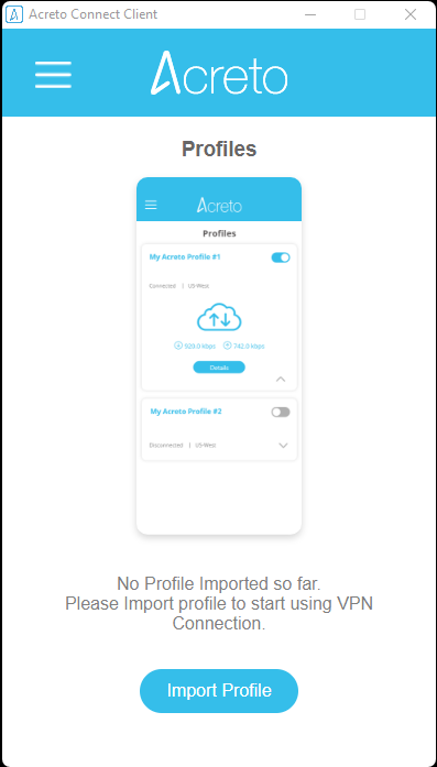
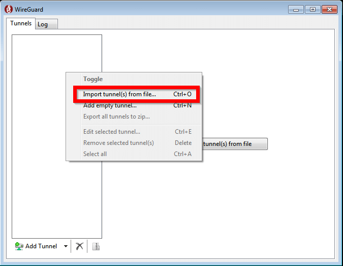
- Click on the Import Profile button.
- You will see three options to connect import the profile: Code, URL, and the file. In this case, we will use the URL generated in the previous step.
- Paste the configuration link from the Wedge generated in the previous step and click on the Import button
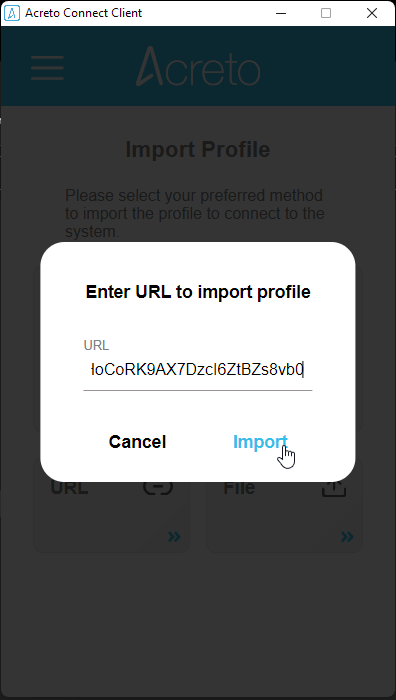
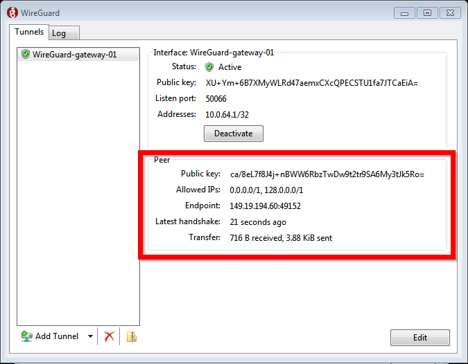
- The Acreto Connect Client will import the profile and atomically connect your device to the Ecosystem.

Your device is now connected to the Ecosystem!
Summary
Acreto Connect Client allows connecting your Thing to the Ecosystem. This method works on every platform and it’s easy to understand for Users.
Please don’t forget to create Security Policy - Policies to allow Outbound traffic for your Thing(s) to connect to the Internet, or to the other devices within your Ecosystem.
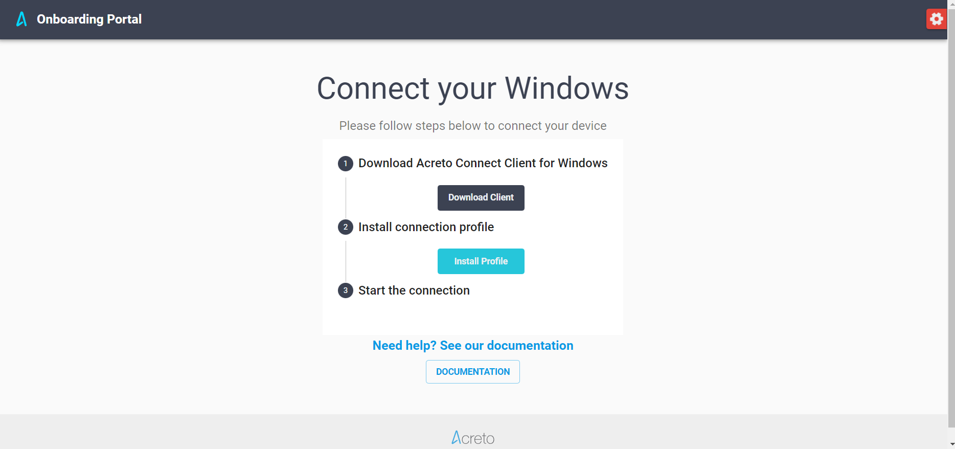
VPN Start Before Logon (SBL)
Before You Start
Overview
Available only for Windows platforms, the Acreto Connect Client Start Before Logon (SBL) establishes the VPN connection before logging onto Windows. The purpose of this feature is while the computer is off the office or when the user is logging onto a new computer remotely. SBL allows remote users to log to Windows using Domain Controlled credentials because the VPN tunnel to the Data-Center is always on.
Note
This feature is available only for version 2.4.0 and newer. Update your ACC if you want to use this option.
Prerequisites
To connect your Windows device to the Ecosystem on the log on you will need:
- Existing Acreto Ecosystem, if you don’t have one learn how to create it.
- Access to Acreto Portal.
- A Windows device that you want to connect to the Ecosystem.
- Acreto Connect Client (minimal version 2.4.0).
How To
Install Acreto Connect Client
At first, you need to download and install the Acreto Connect Client.
-
Go to the download page to get Acreto Connect Client.
-
Install the ACC
-
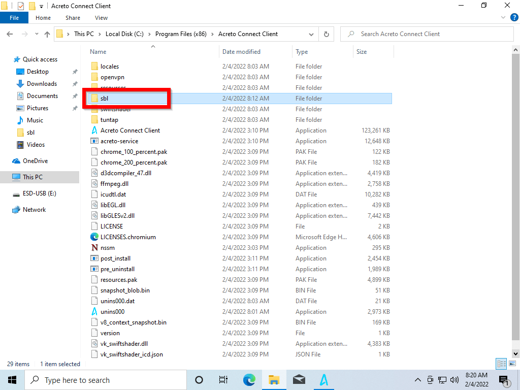
Go to
C:\Program Files (x86)\Acreto Connect Client
to confirm that the sbl directory exists.
-
Run the acc_sbl.reg file - it will add some information into your system registry.
-
Open the Powers Shell with Administrator privileges and run:
Set-ExecutionPolicy -ExecutionPolicy RemoteSigned -Scope LocalMachine
Answer “Y” for the question in PowerShell, then run:
cd "C:\Program Files (x86)\Acreto Connect Client\sbl"
.\sbl.ps1
You will receive confirmation of Acreto-SBL Service creation.
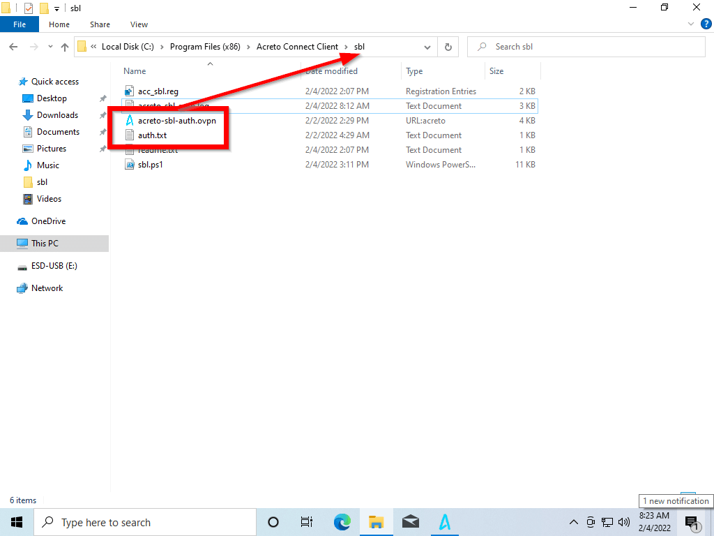
SBL feature will run any profile that you will place in C:\Program Files (x86)\Acreto Connect Client\sbl.
-
Create the profile in Acreto Portal.
-
Download the profile and place it in C:\Program Files (x86)\Acreto Connect Client\sbl directory.
-
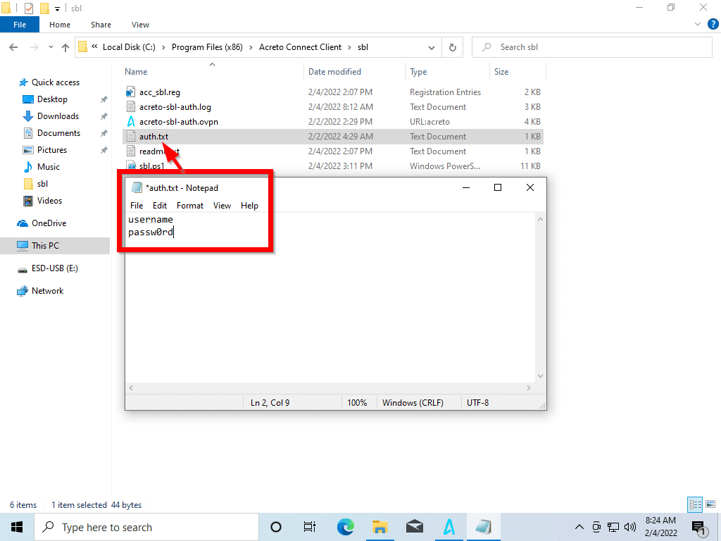
If the profile requires authorization:
-
create auth.txt file and provide the username and password in form:
-
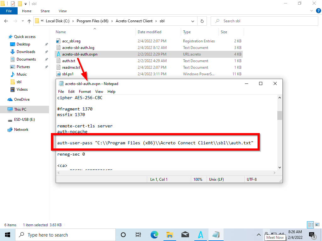
Modify your profile - search for the auth-user-pass line and change it to
auth-user-pass "C:\\Program Files (x86)\\Acreto Connect Client\\sbl\\auth.txt"
Verification
To verify that the feature works correctly, perform the test:
-
Verify using Acreto Portal:
-
Login into Acreto Portal.
-
Choose the proper Ecosystem.
-
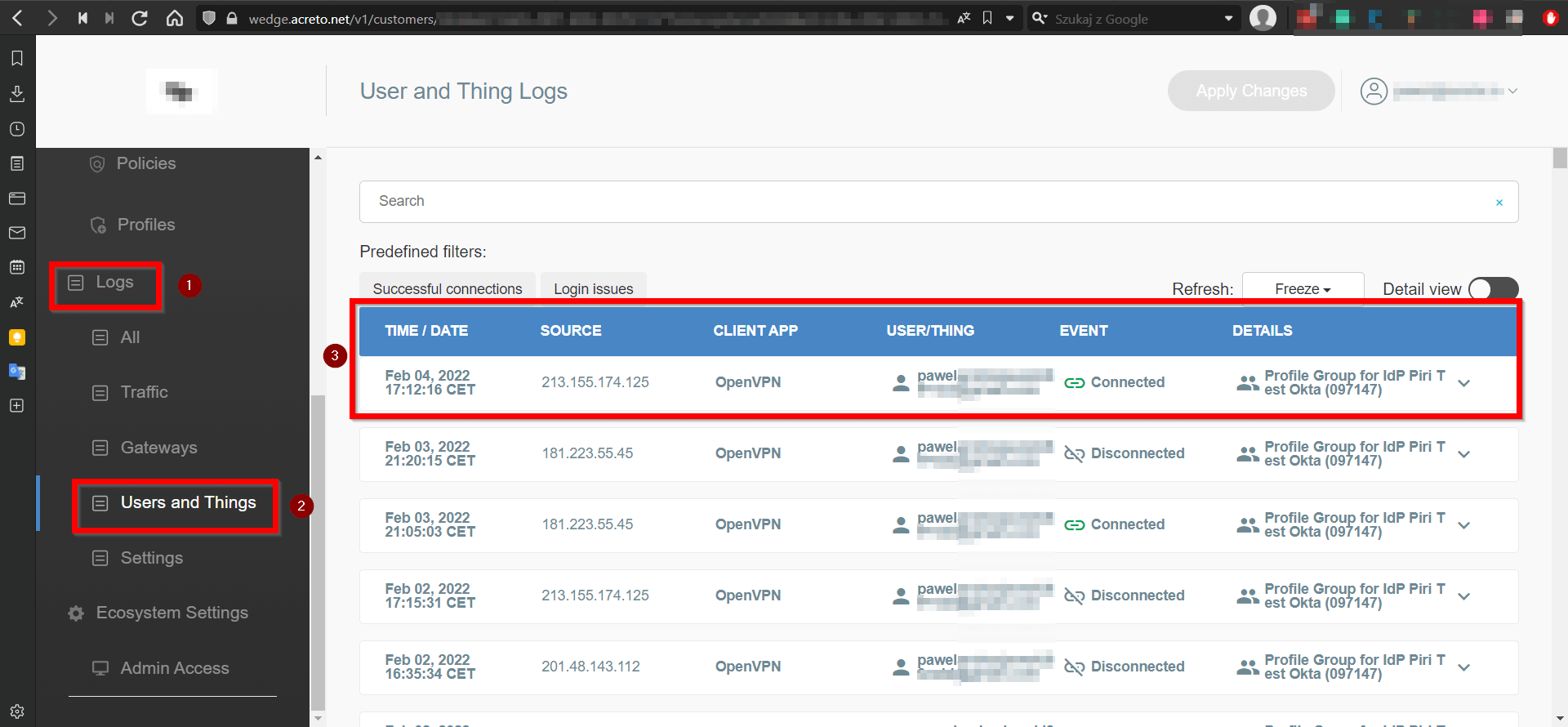
From the left menu, choose Logs(1) > User and Things(2).
-
Set Refresh rate to 5S.
-
Restart the device with the SBL profile.
-
Wait for the login screen on the tested device (do not log in) and the logs, where you should receive information that the profile you placed in the config directory is connected to your Ecosystem (3).
-
Verify using logs:
-
Restart the device with the SBL profile.
-
Wait for a few seconds on the logon screen, then log in.
-
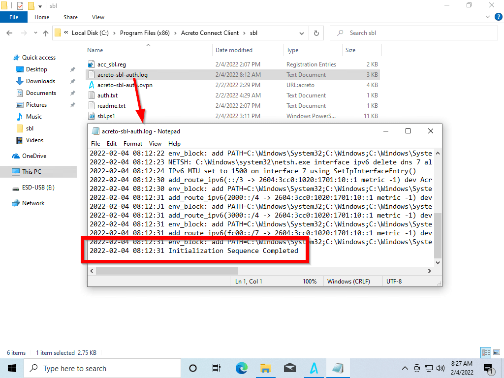
Go to C:\Program Files (x86)\Acreto Connect Client\sbl
-
Find the NAME OF YOUR PROFILE.log and open it to check the logs.
Limitation
We highly recommend using the Split-tunnel profiles.
Once SBL starts the connection User will not be able to disconnect it. If you use the Full-tunnel profile, you will not connect using other full-tunnel profiles.
Summary
Acreto Connect Client allows connecting your Windows device to the Acreto Ecosystem using the SBL feature.
Deep Link
Deep link
To import a profile directly to app from a web browser link, deep link is avalaible with the pattern acreto://
Import Profile using URL
To import from a URL link use the format acreto://import-profile?url=<URL_TO_PROFILE>
Example:
acreto://import-profile?url=https://api-is-rock-solid.acreto.net/v2/tlsvpn/config/openvpn-udp/code/123456
Import Profile using Ecosystem Code
To import from a invite Code use the format acreto://import-profile?code=<6_DIGIT_CODE>
Example:
acreto://import-profile?code=123456
Webserver configuration
To make sure that the VPN profile is opened automatically by the Acreto Connect Client, make sure that the webserver that hosts the .ovpn file sends the correct mime media type in the response HTTP header.
If the header is missing, the .ovpn file may be opened as a text file on Android and iOS devices.
Apache
On Apache servers update mime.conf file and restart the server:
sudo echo "        AddType application/x-openvpn-profile .ovpn" >> /etc/apache2/mods-enabled/mime.conf
sudo systemctl restart apache2
NGINX configuration
On Nginx servers update mime.types file and restart the server:
Edit mime.types config file with your favorite text editor:
nano /etc/nginx/mime.types
Add new mime type
application/x-openvpn-profile .ovpn
Restart the server
sudo systemctl reload nginx
Test
Use any Android or iOS device with Acreto Connect Client installed and tap on the deep link based on your server.
If Acreto Connect Client appeared after the click and the VPN profile is on the list everything works properly.
Install ACC from Windows Command Line
Overview
If your company manages the software using the Active Directory Group Policy Object or tools like Syxsense - ACC is ready to be installed by CMD. This solution lets you quickly onboard your entire team to the Acreto Ecosystem.
Installation and configuration of ACC with the GPO Rules is described in a separate article.
Install and Update Acreto Connect Client with CMD
Acreto Connect Client installer supports parameters that allow the install of software without user action:
Powershell command:
Start-Process ".\Acreto-Connect-Client-v2.9.6.exe" -ArgumentList '/VERYSILENT /NORESTART /SUPPRESSMSGBOXES'
Windows CMD command:
.\Acreto-Connect-Client-v2.9.6.exe /VERYSILENT /NORESTART /SUPPRESSMSGBOXES
Parameters used in install command:
/VERYSILENT - instructs to proceed with installation in the background - no windows will be shown on the system GUI. Alternatively, it may be replaced by /SILENT - in this case, the installation will only show the progress window./NORESTART - disables installer option to restart user device after installation - this option is highly recommended./SUPPRESSMSGBOXES - instructs to suppress any message boxes that appear at installation time and proceed with default options. It only has an effect when combined with /SILENT or /VERYSILENT.
If you need more options, please follow the official documentation for the installer.
Next step
The commands described above can be used to install or upgrade ACC. You can use them in your custom scripts or software management tool.
Install ACC with Group Policy Object
Overview
If your company manages the users by the Active Directory, it’s possible to provide and install Acreto Connect Client using Group Policy Object. ACC is ready to be installed and configured by GPO rules. This solution allows you to quickly onboard the whole of your team to the Acreto Ecosystem.
This article consists of two parts:
- Install Acreto Connect Client with Group Policy Object
- Importing Profile into Acreto Connect Client with Group Policy Object
Prerequisites
Note
This feature is available only for version 2.4.3 and newer. Update your ACC if you want to use this option.
To complete these tutorial steps, the following items are required:
- Windows Server machine
- Basic knowledge of Windows Server configuration
- Active Directory setup experience
Install Acreto Connect Client with Group Policy Object
Acreto Connect Client uses *.EXE installer - this means that you cant use the default way of software installation for GPOs. To install ACC you need to create a Scheduled Task to run the installation script. Scheduler task allows to run the script and install software with administrator privileges. What’s more important - installation is completely invisible for the user.
How to
-
First, create the shared folder that will be available for the users.
-
Download the last version of Acreto Connect Client for Windows.
1.Rename the installer to Acreto-Connect-Client.exe and place it in a shared folder. Installation script also takes care of the updates - it will read the installation version and compare it to the one existing on the users device - if the available version is newer, it will install it.
-
On the domain controller server, create an acreto_install.ps1 file with the below content:
# ADD YOUR VALUES HERE
$InstallPath = 'C:\Program Files (x86)\Acreto Connect Client' #local installation path
$InstallerFile = '\\SERVER\acc\Acreto-Connect-Client.exe' #ACC installer path shared in internal network
# END

IF (Test-Path -Path $InstallPath) {
#if path exists then...
$InstallPathExe = 'C:\Program Files (x86)\Acreto Connect Client\Acreto Connect Client.exe' #local installation binary
$update = ((Get-Item $InstallerFile).VersionInfo.ProductVersion) #Version of ACC available on server
$current = ((Get-Item $InstallPathExe).VersionInfo.ProductVersion) #Version of ACC available on server

IF ([System.Version]"$update" -gt [System.Version]"$current"){
   #if update is available than install
   & "$InstallerFile" /qn /SILENT /norestart INSTALLSTARTMENUSHORTCUTS=1 DISABLEADVTSHORTCUTS=0
   & 'C:\Program Files (x86)\Acreto Connect Client\post_install.exe'-y /qn /SILENT /norestart
} ELSE {
   #If thers no update, exit.
   EXIT
}
} ELSE {
& "$InstallerFile" /qn /SILENT /norestart INSTALLSTARTMENUSHORTCUTS=1 DISABLEADVTSHORTCUTS=0
& 'C:\Program Files (x86)\Acreto Connect Client\post_install.exe'-y /qn /SILENT /norestart
}
-
In Group Policy Management, create a new Group Policy under your domain.

-
Edit the GPO by right-clicking on it and select Edit.
-
Navigate to User Configuration > Preferences > Control Panel Settings > Scheduled Tasks

-
Click Right Mouse Button on Scheduled Task panel and choose New > Immediate Task (At least Windows 7)

-
In task creation widow set:
-
Name: ACC installer
-
When running the task, use the following user account: click on Change User or Group button and inpute SYSTEM as a user and click on Check names button. As a Result you should recive the NT AUTHORITY\System.
-
Check: Run whether user is logged or not
-
Check: Run with highest privileges
-
Configure for: Windows 7, [..]

-
Go to Actions tab and click on New… tab
-
Action: Start a program
-
Program script: %windir%\System32\WindowsPowerShell\v1.0\powershell.exe - path to the PowerShell
-
Add arguments: -Noninteractive -ExecutionPolicy Bypass –Noprofile -file PATH-TO-acreto_install.ps1 - make sure that path to script will be available throught the network.
-
Click Ok butten and the sace whole task.

Result
As a result, the scheduled task will be run regularly on users devices and run the installer script. Installer script working with system privileges will check if ACC needs to be installed or updated.
Importing Profile into Acreto Connect Client with Group Policy Object
Acreto Connect Client is already installed on the user’s computer. To establish a connection the ACC required a profile with configuration. Create the policies to download the correct Profile for ACC.
How to
-
Add the script to import the profile, navigate to User Configuration > Policies > Windows Settings > Scripts ( Logon / Logoff ):

Copy and paste the below code into acreto_profile_deep_link.ps1:
Start-Process "acreto://import-profile?code=123456"
Note
This action needs to be made on user log-on because it required Internet access to download the profile data.
-
Navigate to Computer Configuration > Policies > Administrative Templates > All Settings
-
Do the following change under settings:
- Configure Logon Script Delay: Enabled
- Turn on Script Execution: Enabled

-
Double click on Turn on Script Execution and modify its setting. Make sure that the Execution Policy is set to Allow all scripts. If you want to run only signed scripts it is also possible, but you will need to sign in with your certificate before running it.

This script will be executed on the user login. ACC import profile by the deep link. No user actions are required.
Next step
All computers should be configured to use Acreto Connect Client. The user needs to use their credentials to login into the Ecosystem (if the profile needs that).
If users were imported from the AD the credential should be the same as stored in AD.
Subsections of IPsec Gateway
AWS EC2 - Automatic IPsec Configuration
Prerequisites
- Acreto Ecosystem
- Basic knowledge about AWS VPC.
- Basic knowledge about AWS EC2.
AWS - Create VPC
- Login to AWS console.
- follow the official guide and create a VPC.
- If your VPC already exists, make sure that there’s at last one subnet.
- Open setting for VPC (Networking & Content Delivery section) or use the search option to find VPC settings.
- Please note the network address of this subnet.
Acreto - Create Gateway
- Log in to Acreto Portal.
- Create new Gateway - IPSec type - follow this article.
- When configuring new Gateway add network(s) - same as VPC subnet in Local networks area.
AWS VPC - Create EC2 and Install Acreto Gateway Software
- Create new EC2 with Ubuntu in selected VPC.
- Connect with SSH to the new EC2 instance (username:
ubuntu)
- Copy and paste the command for acreto auto installation script - don’t press ENTER yet.
- Acreto - Generate IPsec config and copy the link
- Paste the link in the SSH terminal and press ENTER
AWS VPC - Update VPC Subnet Route Table
- Open the VPC panel on AWS, and from the left menu choose Route Tables.
- Modify the VPC Route Table - read more
- Info: A routing table that’s associated with a subnet for the VPC.
- Add
100.64.0.0/16 on the Route Table
- Destination
100.64.0.0/16.
- Target Instance - “Acreto Gateway” (
eni- of that instance).
- If there are more AZ (Availability Zones), update the route table for the other subnets as well.
- Update AWS Security Group to allow all inbound and outbound traffic for Acreto subnet
100.64.0.0/16- Allow all traffic from/to this subnet, because we control the traffic on Acreto Security Policies
AWS EC2 - Disable source/destination checks for EC2 instance
- To disable source/destination checking using the console
- Open the Amazon EC2 console at https://console.aws.amazon.com/ec2/.
- In the navigation pane, choose Instances.
- Select the NAT instance, choose Actions, Networking, Change Source/destination check.
- Verify that source/destination checking is stopped. Otherwise, choose Stop.
- Choose Save.
- Read more on AWS
- Create a Security Policy to allow traffic from selected Gateway and/or Profile Group(s) to the VPC subnet
AWS Site-to-Site VPN using Virtual Private Gateway
Before You Start
Overview
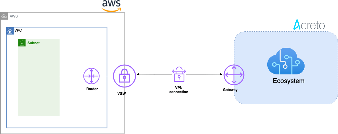
This article describes how to configure a Route-Based Site-to-Site IPsec VPN between an Acreto Ecosystem and the Amazon Web Services (AWS) Virtual Private Cloud (VPC) using static routing:
- Network Diagram
- Concepts and Glossary
- Prerequisities
- The Purpose of Site-to-Site IPsec VPN
- Configuring Acreto Gateway object for IPsec AWS Site-to-Site VPN tunnel
- Setting up the Amazon AWS Virtual Private Cloud and VPN Connection
- References and Related Articles
Network Diagram
Concepts and Glossary
- IPsec VPN tunnel: An encrypted link where network traffic can pass between Acreto Ecosystem and AWS VPS.
- Customer gateway: An AWS resource that provides information to AWS about the Acreto IPsec Gateway object.
- Virtual private gateway: The VPN concentrator on the Amazon side of the Site-to-Site VPN connection.
Prerequisites
In order to setup IPsec Site-to-Site VPN tunnel between Acreto Ecosystem and AWS VPS you need:
- Access to Active Acreto Ecosystem
- Access to AWS Management Console
The Purpose of Site-to-Site IPsec VPN
Acreto as a Cloud Provider allows to connect and integrate multiple networks, both physical and virtual. All connections require stable and secure links. Virtual (EC2) Instances running on Amazon VPC can’t communicate securely with your own (remote) network by default. It is possible to connect your network to Acreto Ecosystem and then you can enable access to your remote network from your VPC by creating an AWS Site-to-Site VPN (Site-to-Site VPN) connection, and configuring routing to pass traffic through the connection.
Acreto Ecosystem configures the routing automatically and passes the traffic between AWS VPC and your network. Additionally, the traffic is scanned by the Acreto Threat Engine to block suspicious traffic and malware.
Tip
AWS Site-to-Site VPN limitations: IPv6 traffic is not supported for VPN connections on a virtual private gateway. An AWS VPN connection does not support Path MTU Discovery. In addition, take the following into consideration when you use Site-to-Site VPN.
Use the following procedures to manually set up the AWS Site-to-Site VPN connection on Amazon AWS.
You can create a Site-to-Site VPN connection with either a virtual private gateway or a transit gateway as the target gateway.
Step 1: Create VPC
Use existing VPC or create a new VPC using the steps below :
-
Login to AWS console.
-
Goto the region where you want to create your VPC.
-
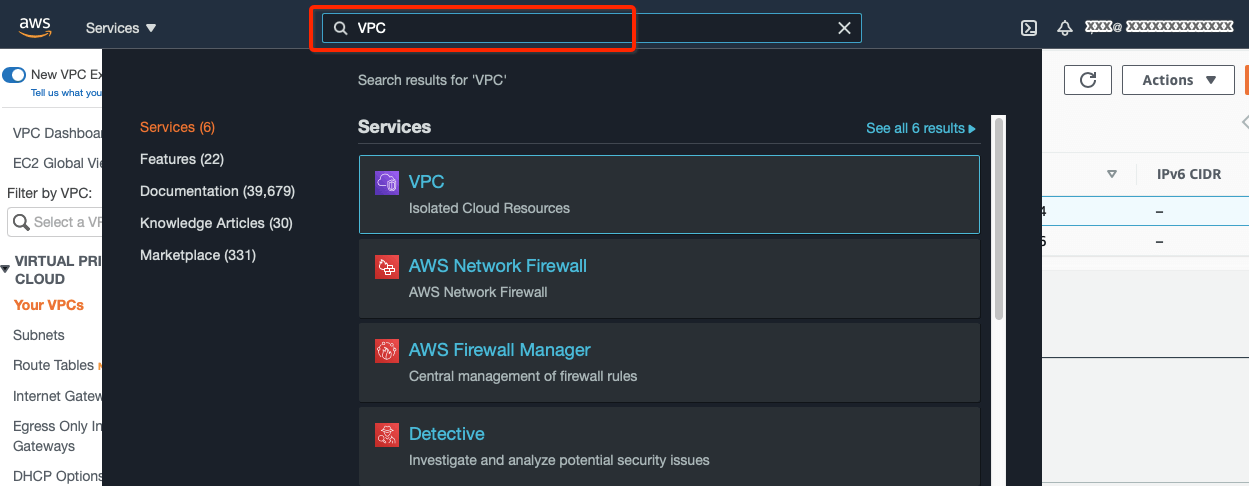
Search VPC in the Services search tab.
-
From the VPC Dashboard, click Your VPCs under VIRTUAL PRIVATE CLOUD in the left sidebar and click Create VPC
-
Create a VPC with the following values:
- IPv4 CIDR Block: 172.16.0.0/22
- IPv6 CIDR Block: No IPv6 CIDR Block
- Tenancy: default
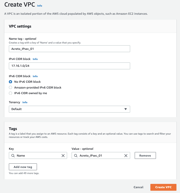
-
Click Create VPC
Step 2: Create Subnet
Now create a new subnet in the VPC address range. If you want to use an existing subnet, you can skip this step and use the pre-existing subnet in subsequent steps.
-
From the VPC Dashboard, click Subnets under VIRTUAL PRIVATE CLOUD in the left sidebar and click Create Subnet
-
Select the new VPC created in the Step 1 or your existing VPC in the VPC ID options.
-
Create a new Subnet under Subnet settings with the below details :
- Availability Zone: No preference
- IPv4 CIDR block: 172.16.1.0/24
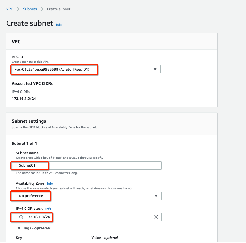
-
Click Create Subnet button
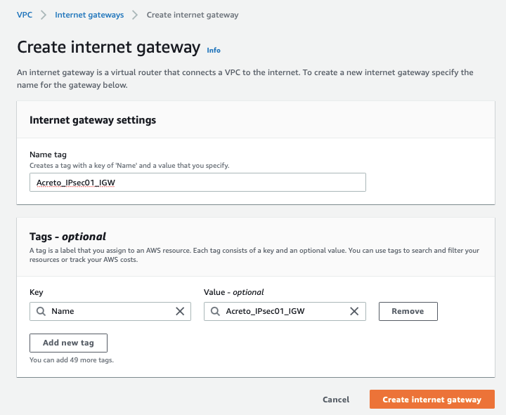
Step 3: Create Internet Gateway
-
From the VPC Dashboard, click Internet Gateway under VIRTUAL PRIVATE CLOUD in the left sidebar and click Create Internet Gateway
-
Give the name for the Internet gateway and click Create internet gateway
-
Select the Internet gateway and click Actions and Attach to VPC
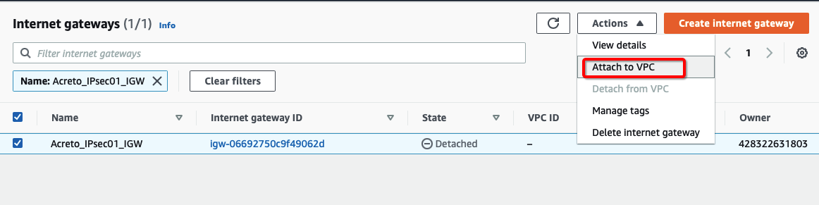
-
Assign your VPC

-
Click Attach internet gateway.
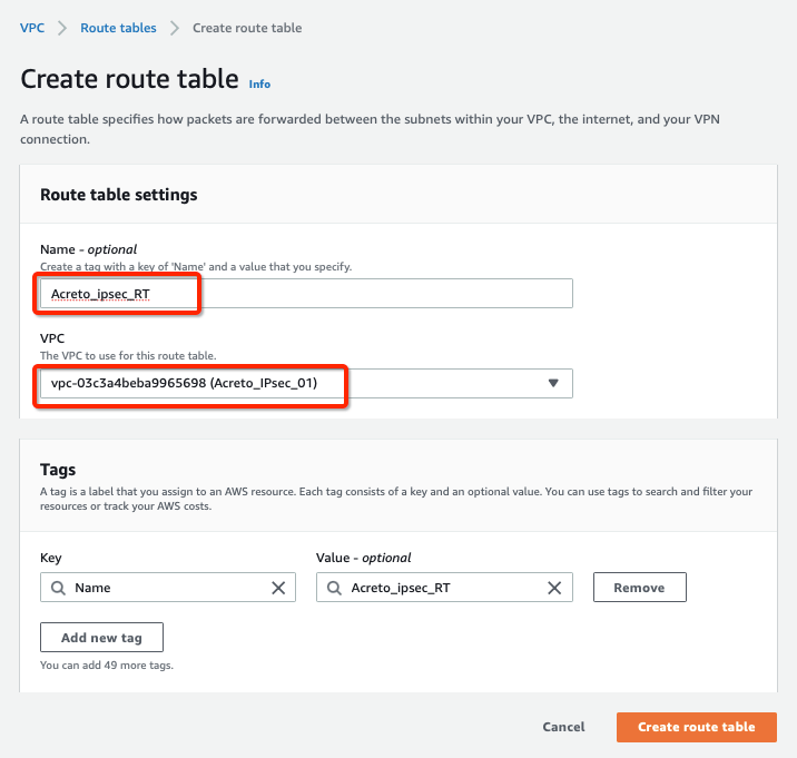
Step 4: Create Route Table
Configure Route table for the above subnet to reach Acreto’s public IP through Internet Gateway.
-
From the VPC Dashboard, click Route Tables under VIRTUAL PRIVATE CLOUD in the left sidebar and click Create Route Table
-
Create a Route table with the following values:
- Name: Acreto_ipsec_RT
- VPC: Select the VPC created in Step 1
-
Click Create Route Table, with parameters as shown in screenshot below:
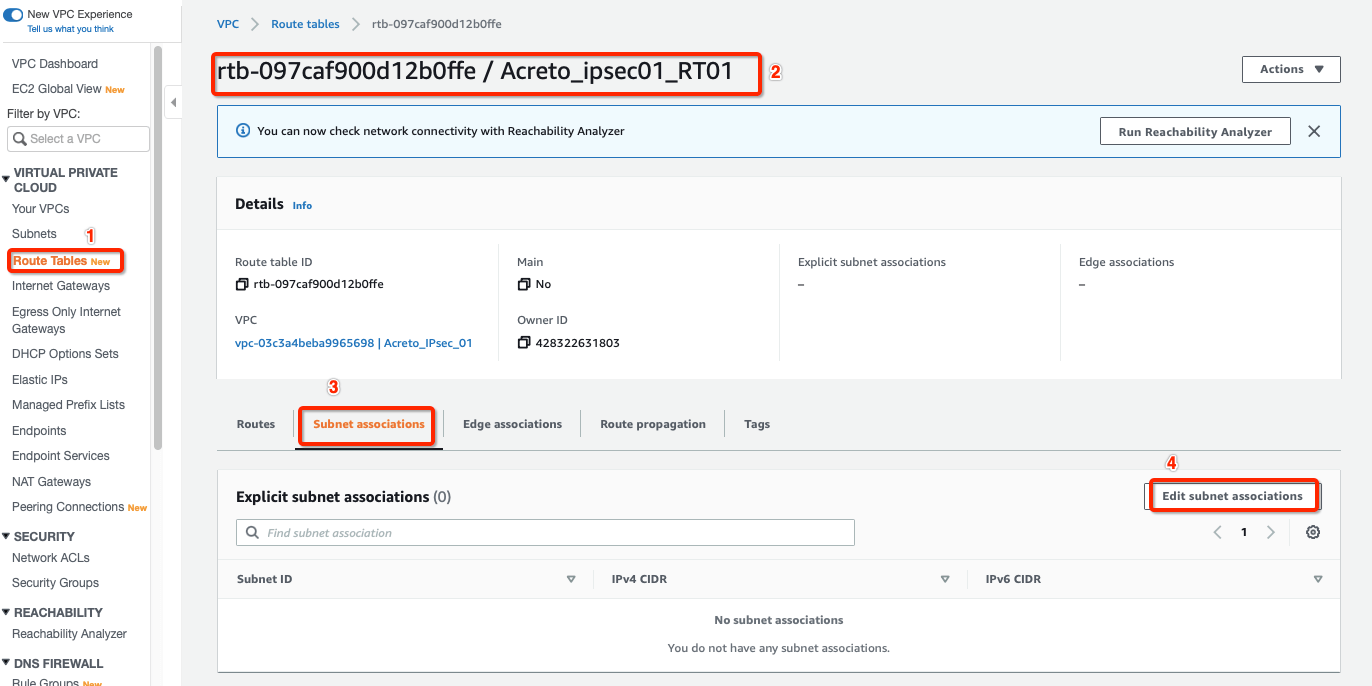
-
Select the Route table created above and click Subnet association, with parameters as shown in screenshot below:
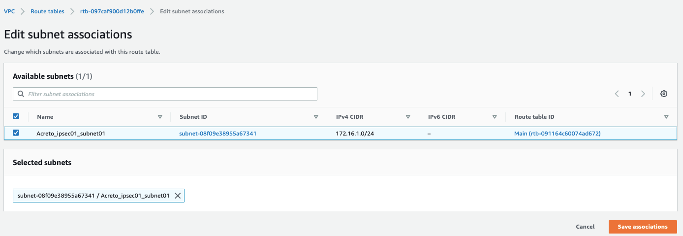
-
Select your Subnet and click Save associations, with parameters as shown in screenshot below:
-
Select the routes and click Edit routes, with parameters as shown in screenshot below:
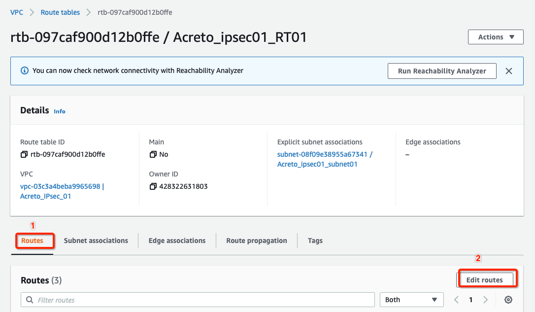
-
Add route for Acreto’s Default Tunnel IP used to form the VPN through the Internet Gateway, with parameters as shown in screenshot below:
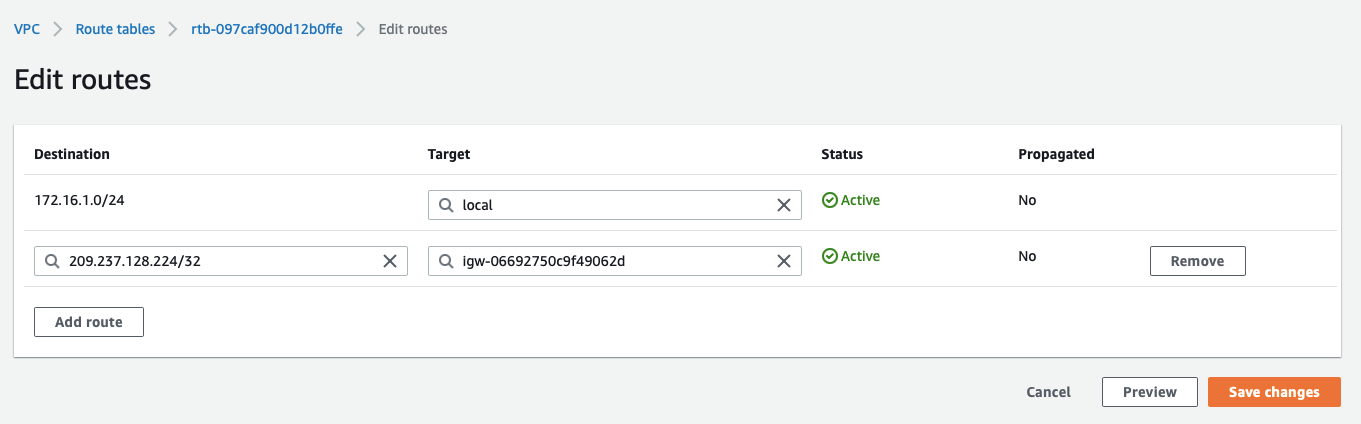
-
Click Save changes.
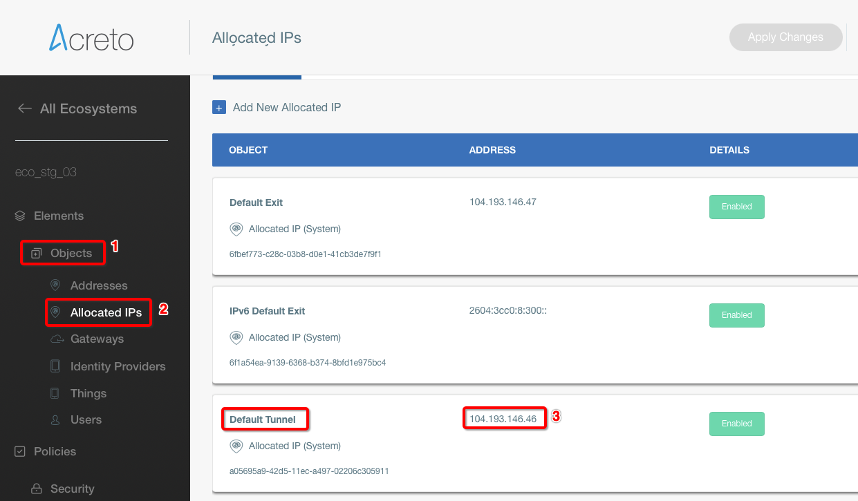
Step 5: Create Customer Gateway
Create new Customer Gateway with Acreto’s public IP.
-
From the VPC Dashboard in the left side bar, goto VIRTUAL PRIVATE NETWORK (VPN) » Customer Gateways
-
Click Create Customer Gateway
-
Provide the following values :
- Name: Acreto
- Routing: Static
- IP Address: Acreto’s Default Tunnel IP
-
Click Create Customer Gateway.

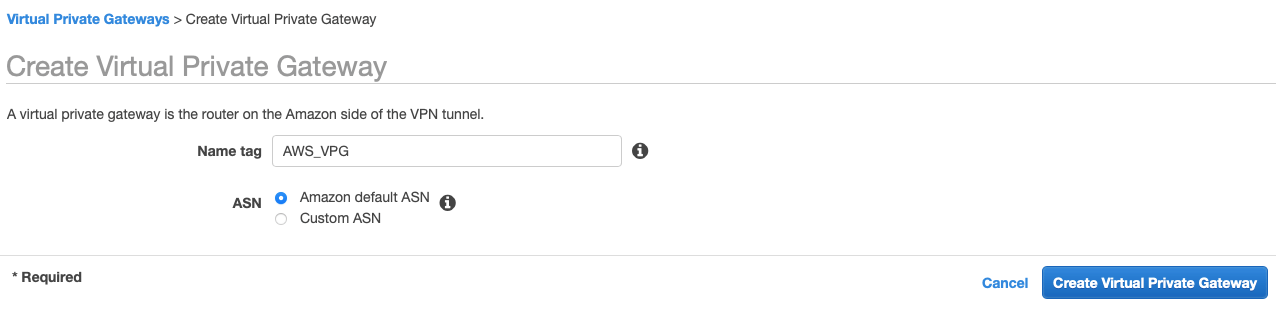
Step 6: Create Virtual Private Gateway
Create a Virtual Private gateway that will be used to form the Ipsec tunnel with Acreto.
-
From the VPC Dashboard in the left sidebar, goto VIRTUAL PRIVATE NETWORK (VPN) » Virtual Private Gateways
-
Click Create Virtual Private Gateway
-
Give the name and click Create Virtual Private Gateway
-
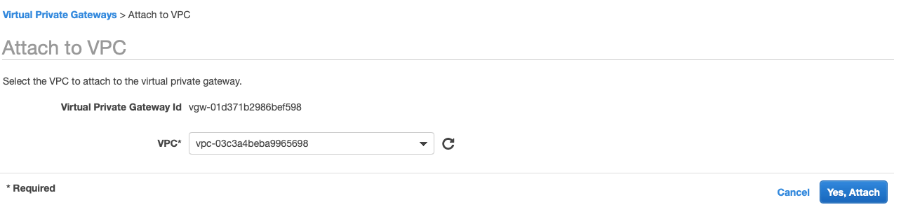
Select the Virtual Private Gateway and click Actions » Attach to VPC
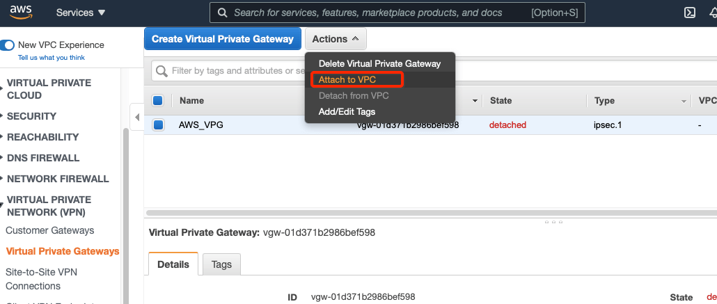
-
Select your VPC and click Yes, Attach button.
-
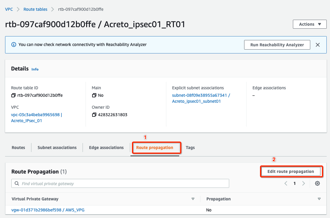
From the VPC Dashboard, click Route Tables under VIRTUAL PRIVATE CLOUD in the left sidebar.
-
Select the route table created in Step 4
-
Select the Route Propagation tab and click the button Edit route propagation.
-
Check Enable
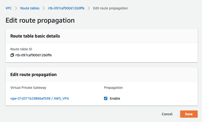
-
Click the Save button.
Tip
This step ensures that the AWS virtual hosts receive a route for the 100.64.0.0/16 network (Acreto Ecosystem Internal network) after the VPN establishes.
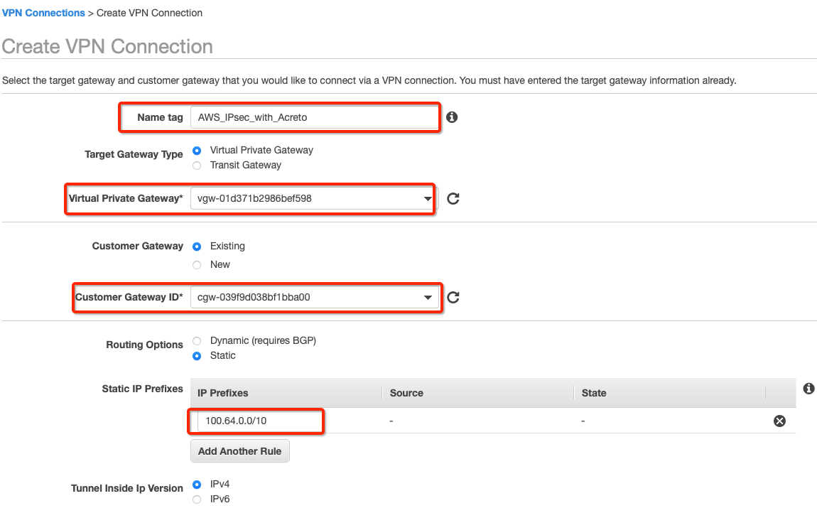
Create a new VPN connection and associate the previously created VGW and CGW.
-
From the VPC Dashboard in the left sidebar, go to VIRTUAL PRIVATE NETWORK (VPN) » Site-to-Site VPN Connections.
-
Click Create VPN Connection.
-
Provide the following values in the tunnel setting:
- Name: Acreto_ipsec
- Target Gateway Type: Virtual Private Gateway
- Virtual Private Gateway: Select the Virtual Private gateway created above
- Customer Gateway: Existing
- Customer Gateway ID: Select the Customer gateway created above
- Routing Options: Static
- Static IP Prefixes: 100.64.0.0/16
-
Click Create VPN Connection.
-
Select the VPN created and click the tab Tunnel Details. Copy the Outside IP address of the tunnel to form a VPN with Acreto.
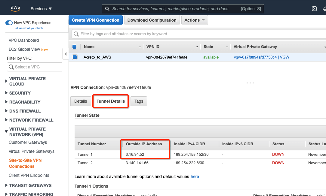
This Outside IP address will be used in the next steps to configure the Acreto gateway on Wedge Ecosystem.
Step 8: Create Acreto Gateway for IPsec
Create Gateway on Ecosystem by following the instruction in the link. Provide the following values:
- Type: IPsec
- Category: Data Center
- Model: AWS site-to-site VPN
- Connections from: AWS Tunnel’s Outside IP address
- Local network: local_network
- Save and Commit the changes.
Step 9: Read the Configuration
-
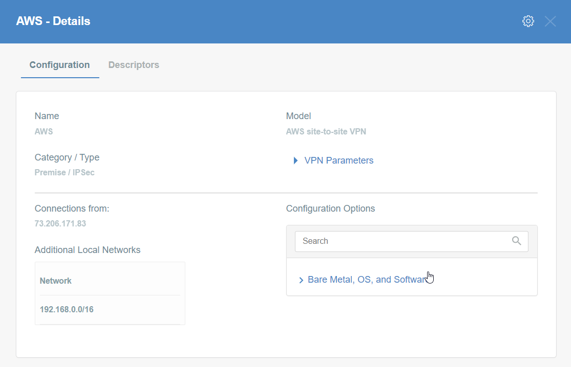
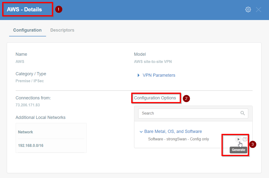
Click the gateway created on wedge.
-
Click the Play button under Configuration Options to generate the strongSwan Config.
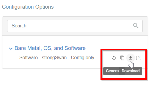
-
Once the Config file is generated, click the Download button to download the configuration on the local computer.
-
Unzip the downloaded file and copy the psk from the file ipsec.secrets

Step 10: Update AWS VPN tunnel configuration
-
Goto AWS Site-to-Site VPN connections
-
Select the VPN and click Actions » Modify VPN Tunnel Option
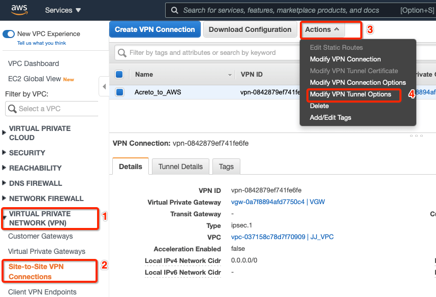
-
Select the tunnel used to create the VPN with Acreto.
-
Update the password copied from the ipsec.secrets file from strongSwan config file downloaded from Wedge
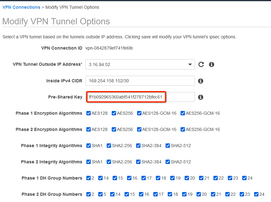
-
In the same window “Modify VPN Tunnel Options” scroll down and select the following action under tunnel configuration:
- DPD Timeout Action: Restart
- Startup Action: Start
-
Click Save
How-to: Update Route Table in AWS
Configure Route table to set the default route to VPN tunnel
-
From the VPC Dashboard, click Route Tables under VIRTUAL PRIVATE CLOUD in the left sidebar
-
Select the Route table and click Edit routes
-
Add the following route :
- Destination: 0.0.0.0/0
- Target: Select the Virtual Private Gateway id
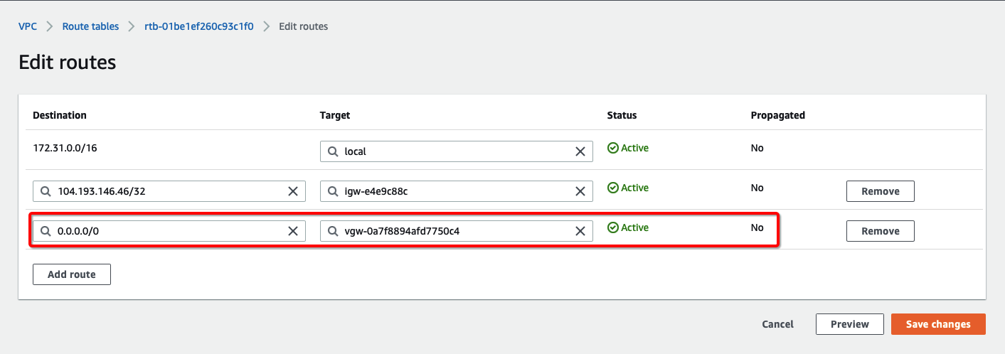
-
Click Save changes.
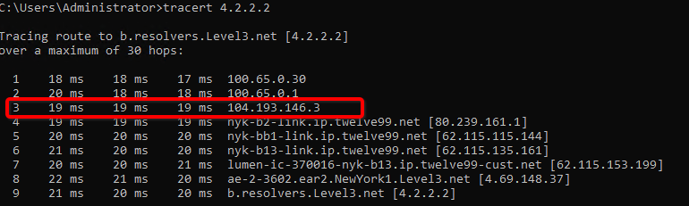
Verify the connections
Once the tunnel connection is successfully established, the status of the connection will be up.
-
To verify on AWS, navigate to the VPN created under VIRTUAL PRIVATE NETWORK (VPN) » Site-to-Site VPN Connections .
-
Verify the following:

-
Do a traceroute or equivalent command from an internal server to public IP like 4.2.2.2. It should show Acreto’s IP in the path.
References and Related Articles
What is AWS Site-to-Site VPN?
Summary
Acreto IPsec Gateway allows to set up VPN tunnel to connect Acreto Ecosystem with Amazon Web Services (AWS) Virtual Private Cloud (VPC).
Azure Site-to-Site connection using VPN Gateway
Before You Start
Overview
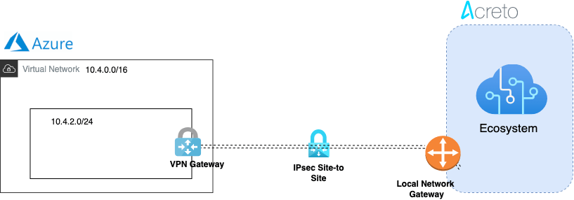
This article describes configuring a Route-Based Site-to-Site IPsec VPN between an Acreto Ecosystem and Azure network.
Network Diagram
Pre-requisite
To set up an IPsec Site-to-Site VPN tunnel between Acreto Ecosystem and Azure, you need:
- Access to Active Acreto Ecosystem (Wedge)
- Access to Azure Portal
Use the following procedures to set up the Azure Site-to-Site VPN connection manually.
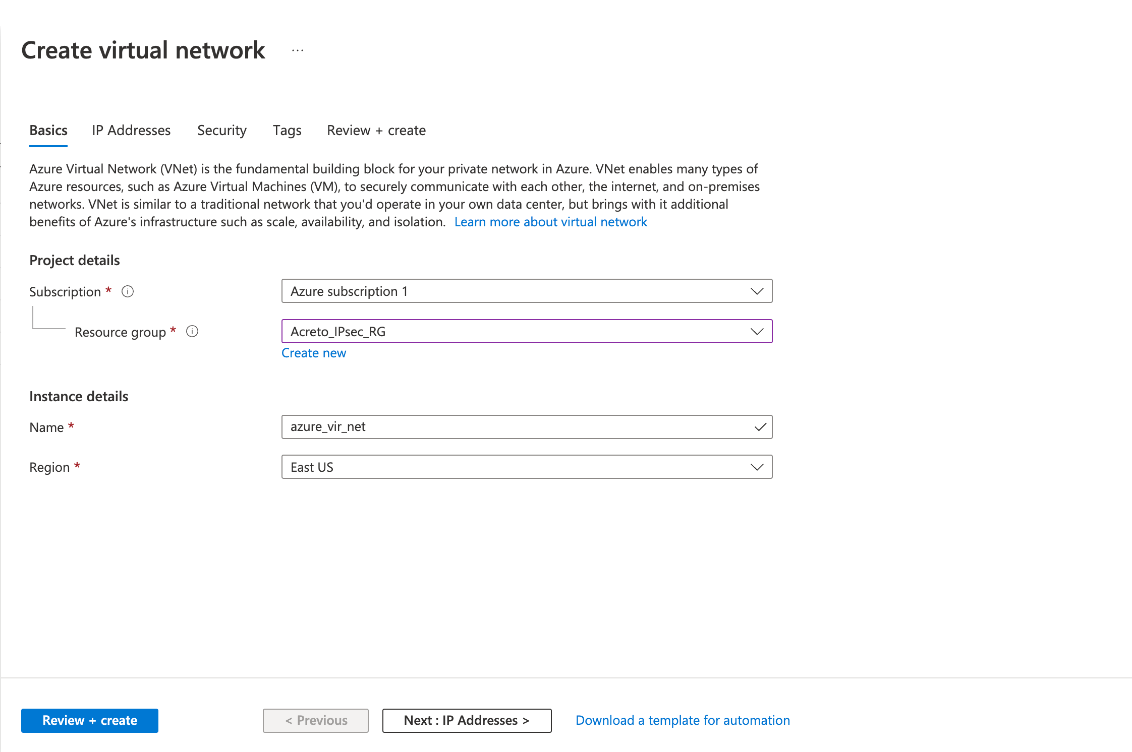
Step 1: Create a virtual network
Use an existing virtual private network or create a new virtual private network using the steps below:
- Login to Azure Portal
- Click on Create a resource
- Click on Networking from the left sidebar.
- Click on Virtual Network
- Fill in the following fields in the Basics tab.
- Project details
- Subscription
- Resource group
- Instance details
- Name
- Region
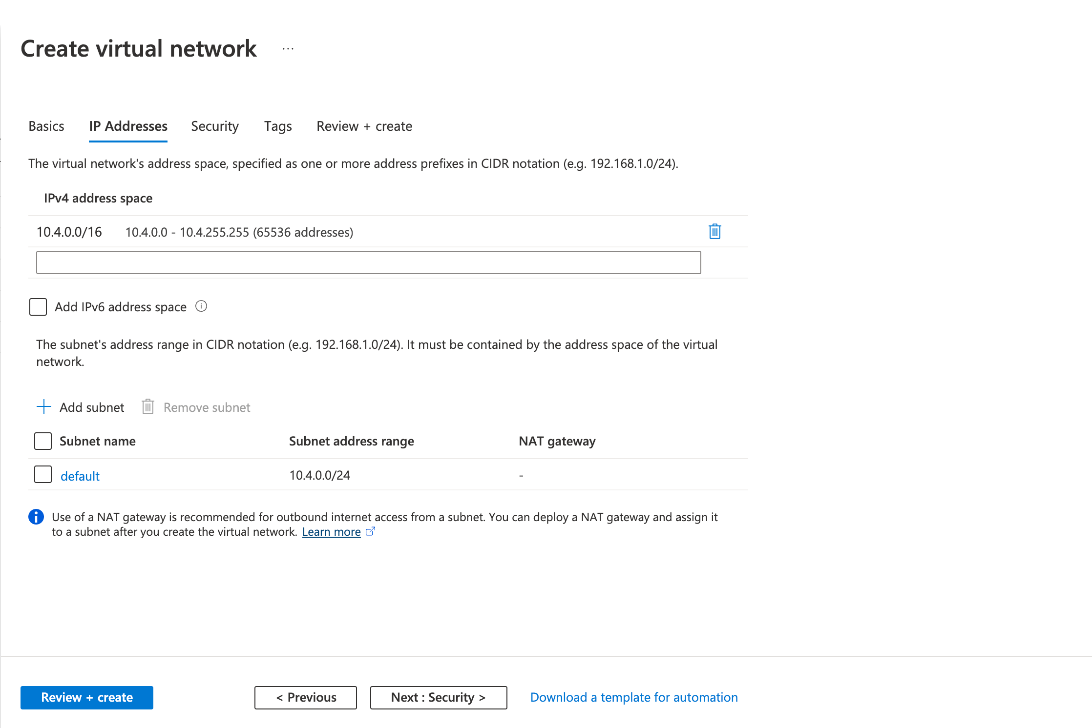
- Fill in the following fields in the IP Addresses tab
- Address space
- Subnet Name
- Subnet Address range
- Review the configurations on the Review + create tab and click Create
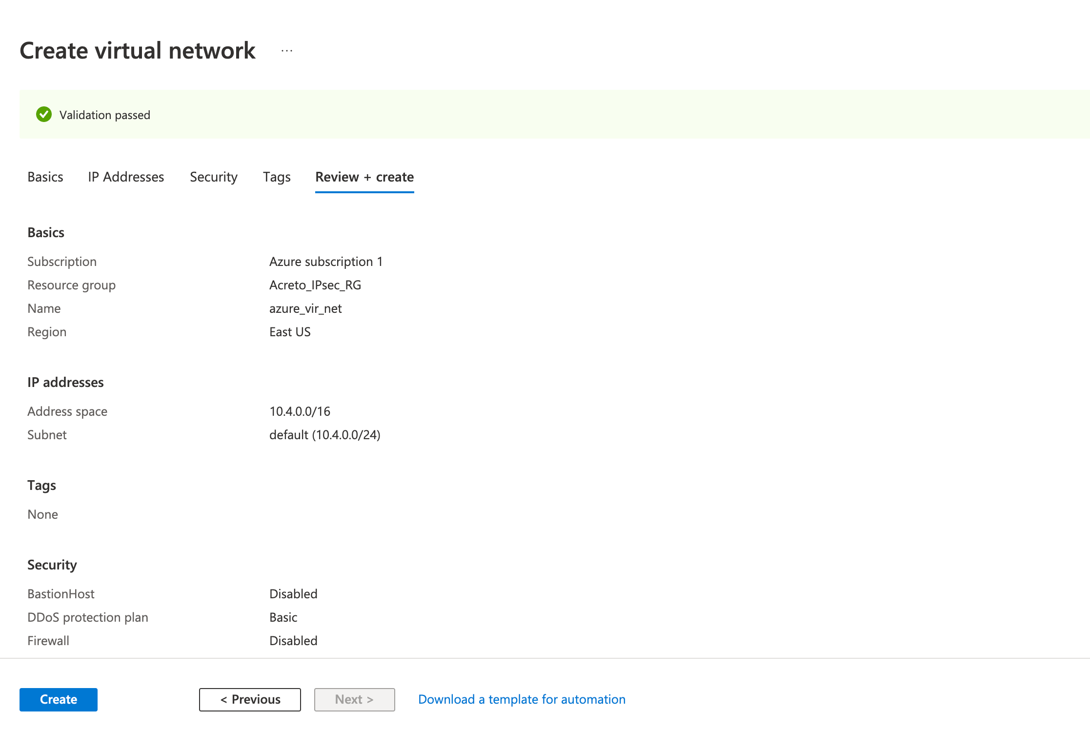
Wait for the deployment to finish and the Virtual Network to be created.
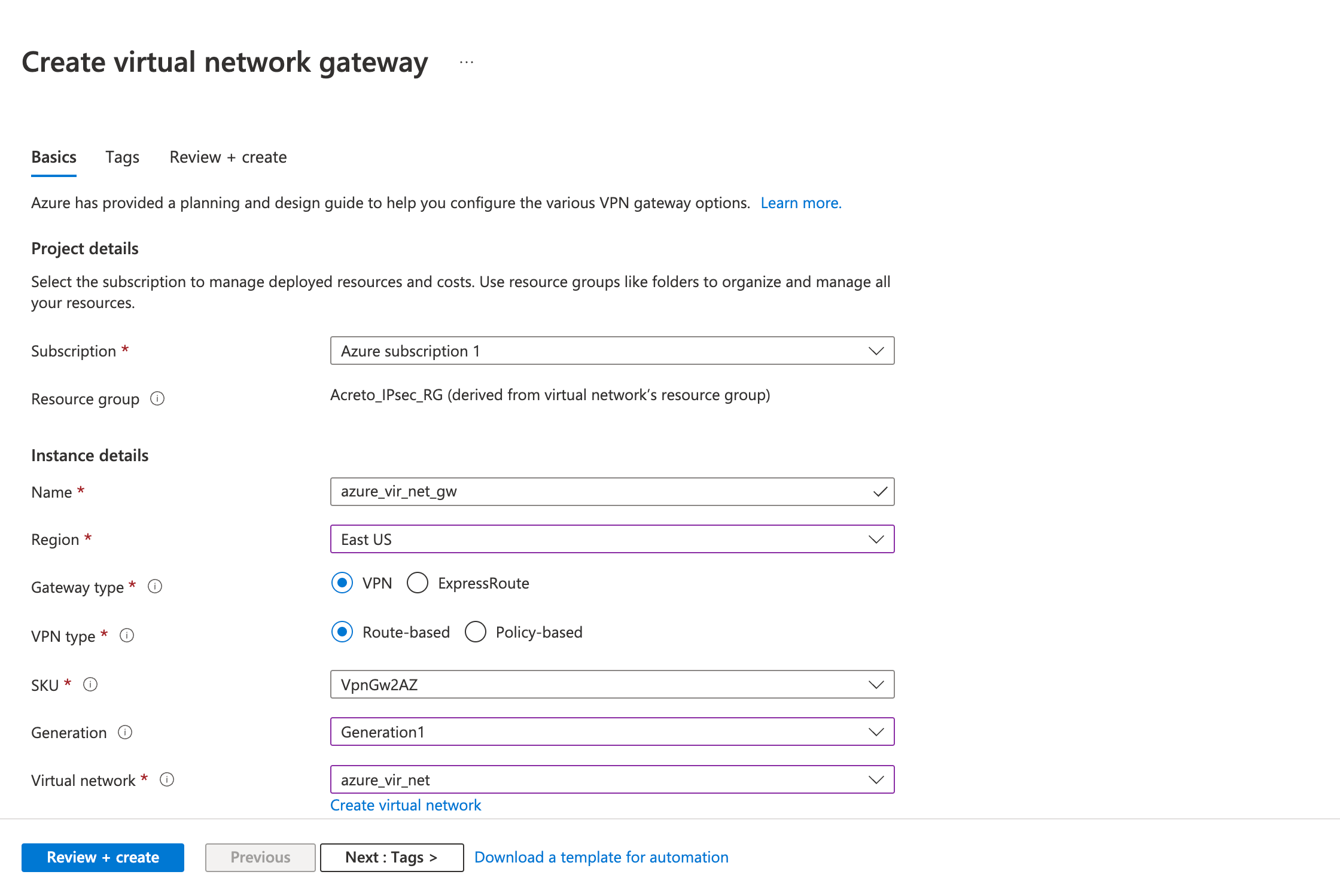
Step 2: Create a VPN gateway
Create the virtual network gateway for your virtual network. Creating a gateway can often take 45 minutes or more, depending on the selected gateway SKU.
- Click on Create a resource
- Click on Networking from the left sidebar
- Click on Virtual network gateway
- Fill in the following fields in the Basics tab.
- Project details
- Instance details
- Name
- Region
- Gateway type: VPN
- VPN type: Route-based
- SKU
- Generation: Generation 1
- Virtual Network: (select the virtual network you created earlier)
- Gateway Subnet address range
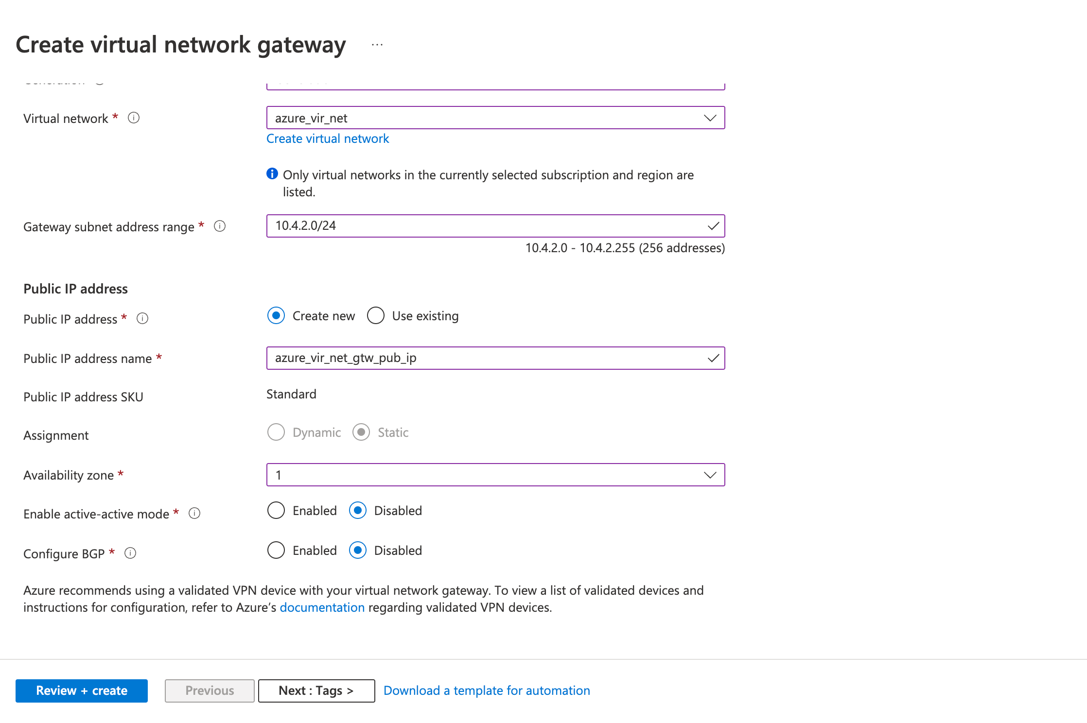
- Public IP address
- Public IP address: Create a new ( or use existing)
- Public IP address name
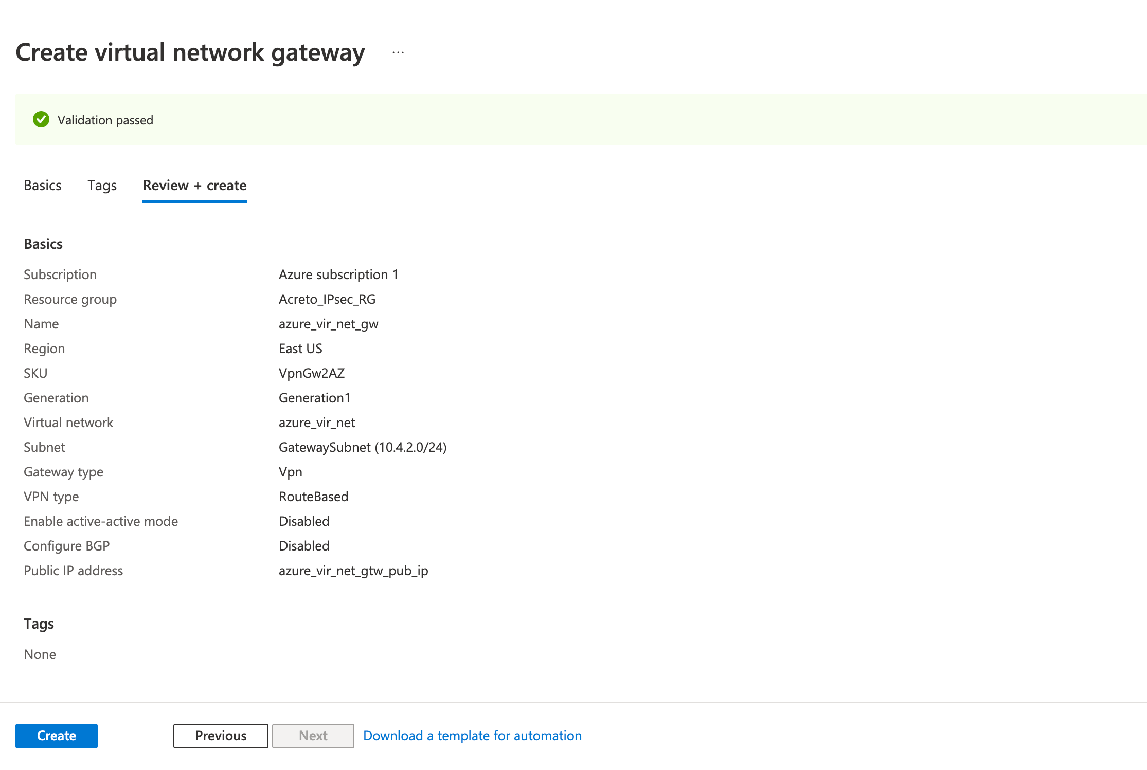
- Review the configurations on the Review + create tab and click Create
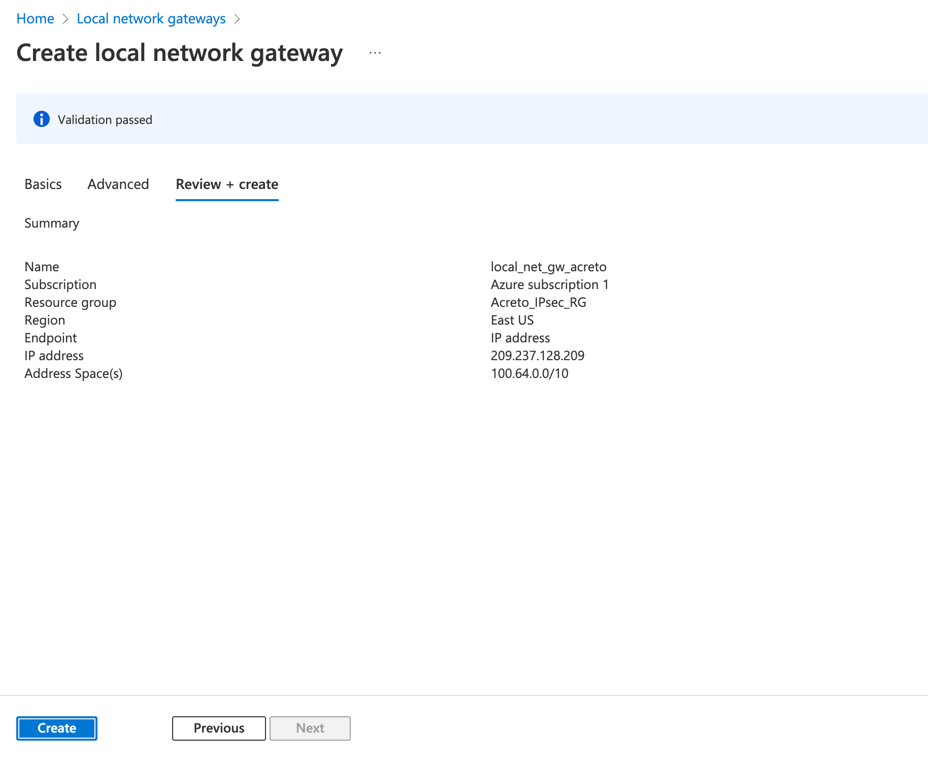
Step 3: Create a local network gateway
The next step is to create a local gateway representing your local network.
- Click on Create a resource
- In the search bar, search for Local Network Gateway
- Click on Create.
- Fill in the following fields in the Basics tab.
- Project details
- Subscription
- Resource group
- Instance details
- Name
- Region
- Endpoint: IP address
- IP Address: Acreto’s Tunnel IP
- Address Space(s): 100.64.0.0/16
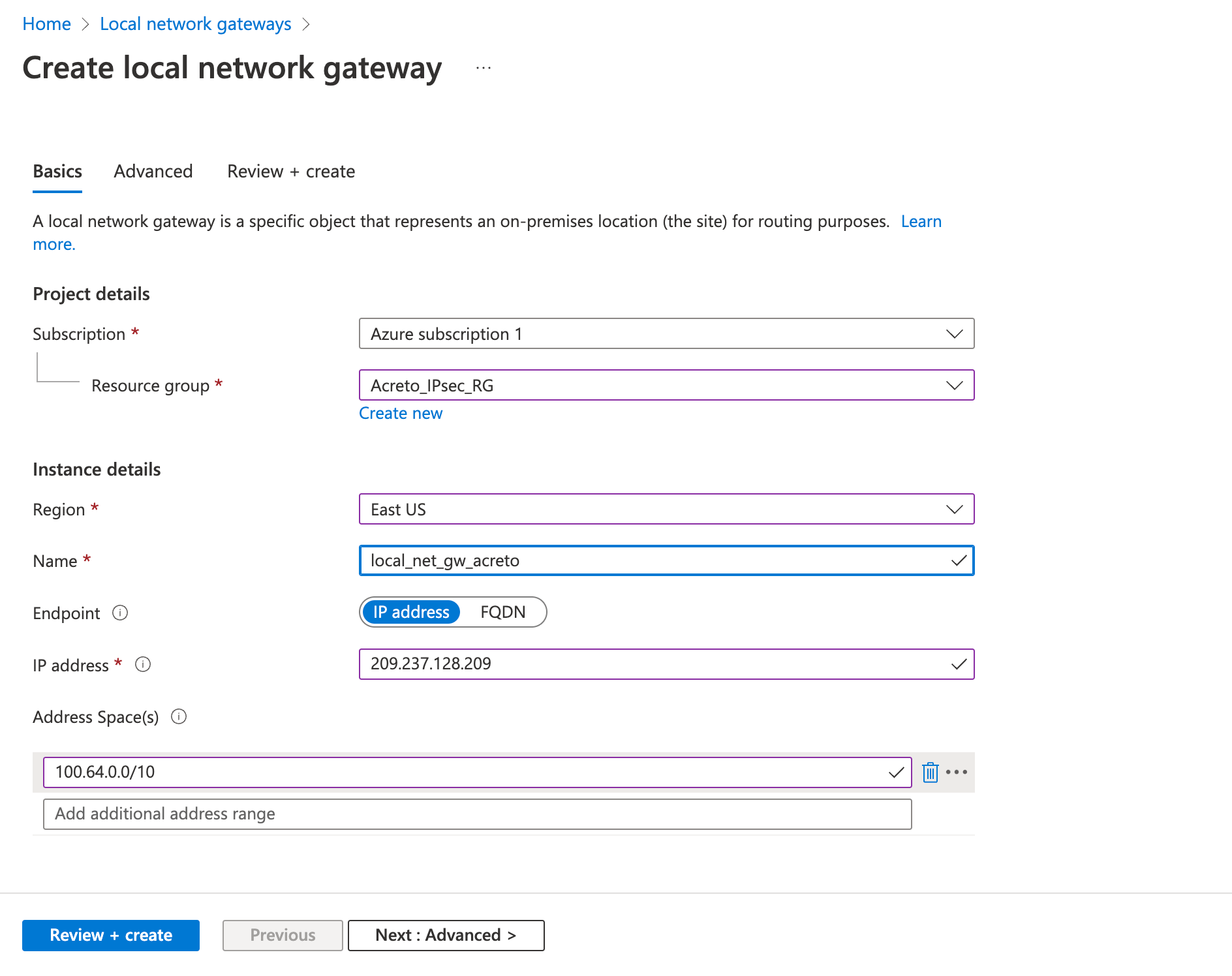
- Review the configurations and click Create
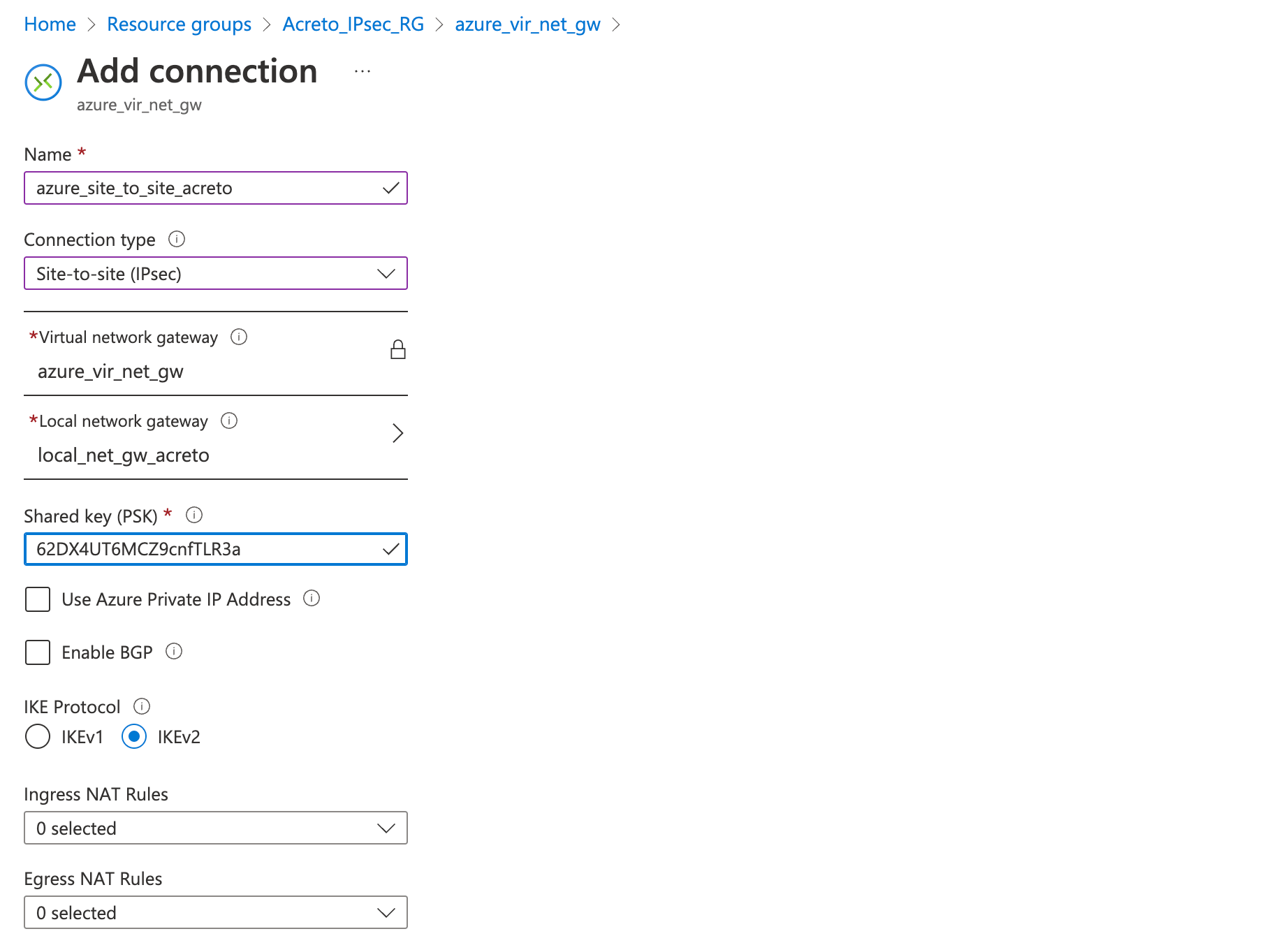
Step 4: Create a VPN connection
This step creates a Site-to-Site VPN connection between your VPN device and the virtual network gateway.
- Click on Create a resource
- In the search bar, search for Connection
- Click on Create.
- On the Basics tab, fill in the following fields:
- Connection type (Site-to-site)
- Subscription (select the same subscription as before)
- Resource group (select the same resource group as before)
- Location (select the same location as before)
- Click on Next
- On the Settings tab, fill in the following fields:
- Virtual network gateway (created in step 2)
- Local network gateway (created in step 3))
- Shared key (create a temporary password)
- Click on Next
- Click on Review + Create
Wait for the deployment to finish and the connection created.
Step 5: Download strongswan configuration
Next, download the VPN configurations from Azure to use it to configure the Acreto gateway.
- Go to the VPN connection created in step 4.
- Click Overview from the left sidebar
- Click Download Configuration
- Select any Device vendor, Device family, and Firmware version of your choice.
- Click the button Download configuration
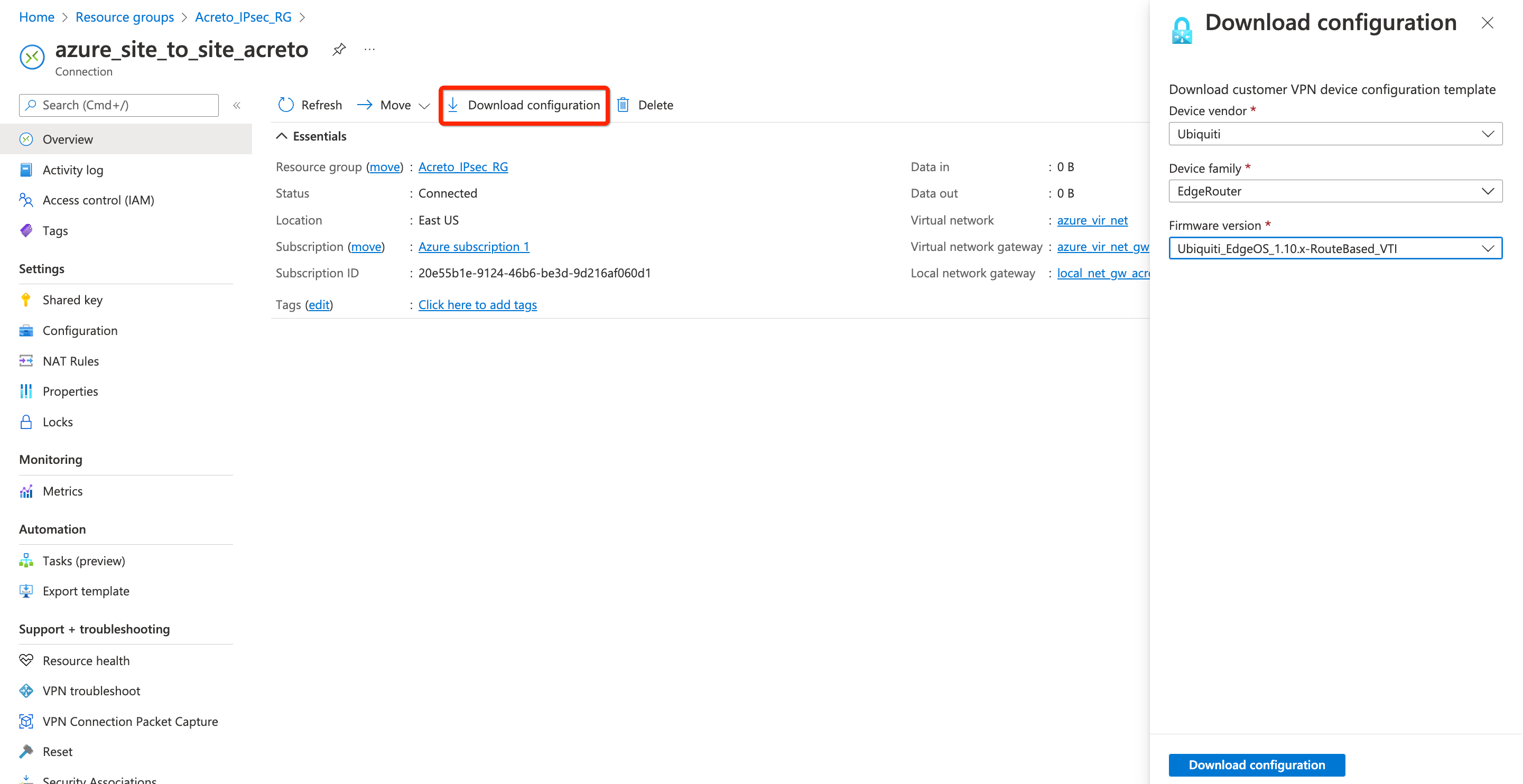
- Open the downloaded file and note the Azure VPN Gateway IP
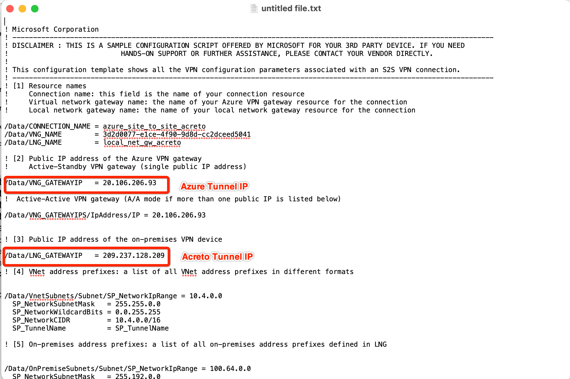
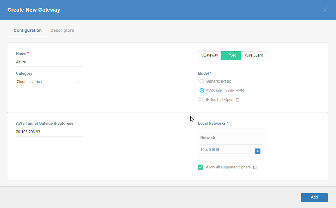
Step 6: Create Gateway on Wedge with option AWS Site-to-Site IPsec and Azure Tunnel IP
Create Gateway on Ecosystem by following the instruction in the link. Provide the following values:
-
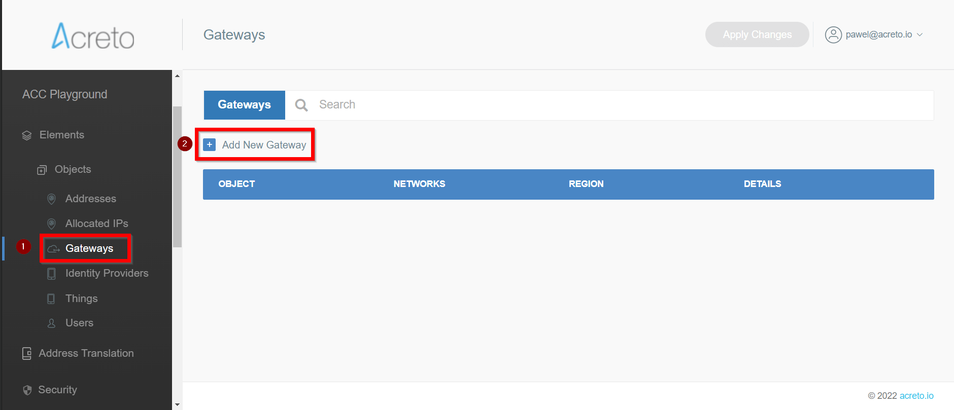
Goto Objects » Gateways
-
Add New Gateway
-
Provide the following information :
- Name: Azure
- Category: Cloud Instance
- Type: IPSec
- Model: AWS site-to-site VPN
- AWS Tunnel Outside IP Address: <Azure VPN gateway IP from Step 5>
- Local Network
Step 7: Read the Configuration
Read the PSK information from the Acreto gateway created in the previous steps.
- Click the gateway created on Acreto in Step 5.
- Click the Play button under Configuration Options to generate the strongSwan Config.
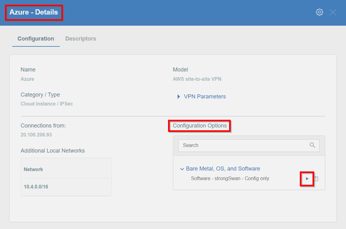
- Once the Config file is generated, click the Download button to download the configuration on the local computer.
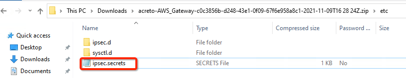
- Unzip the downloaded file and copy the PSK from the file ipsec.secrets
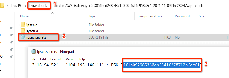
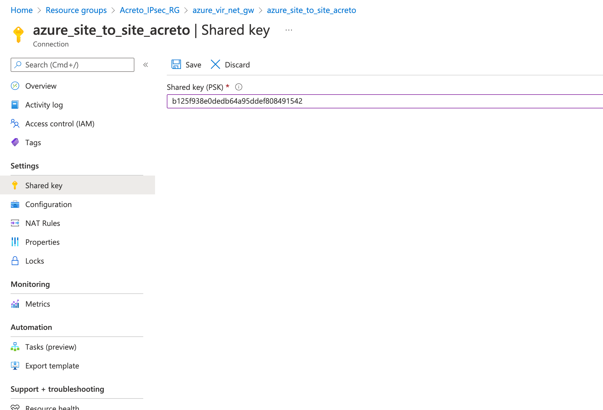
Step 8: Update the PSK from Wedge in Azure VPN
Update the new PSK from the previous step and update the VPN connection on Azure.
- Goto VPN connection created in step 4
- From the left sidebar, click Settings » Shared key
- Update the Shared key (PSK) from the Step 7
- Save
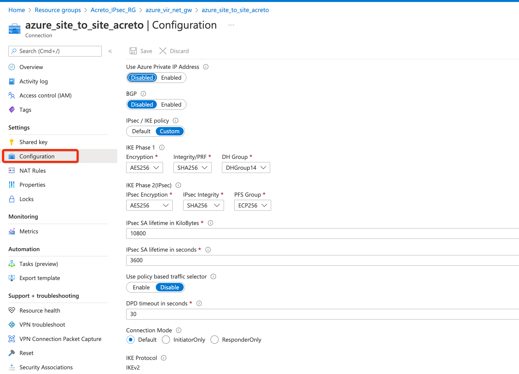
Step 9: Update IPsec Parameter
- Goto VPN connection created in step 4.
- From the left sidebar, click Settings » Configuration
- Update the following
- IPsec / IKE policy - Custom
- IKE Phase 1
- Encryption - AES256
- Integrity/PRF - SHA256
- DH Group - DHGroup14
- IKE Phase 2(IPsec)
- Encryption - AES256
- Integrity/PRF - SHA256
- DH Group - ECP256
- IPsec SA lifetime in seconds - 3600
- DPD timeout in seconds - 30
- Save.
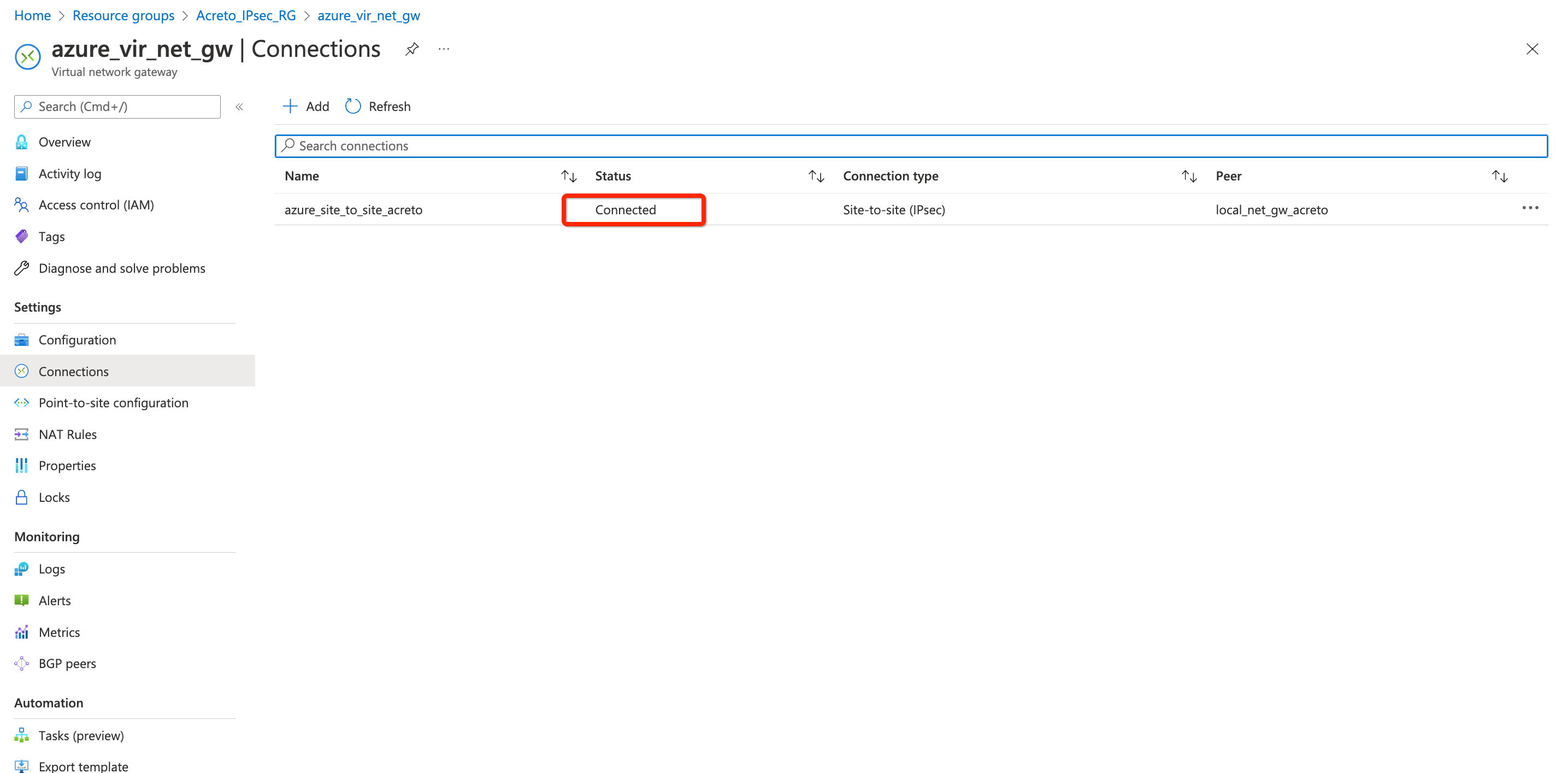
Step 10: Check Connection
- Goto VPN connection created in step 4.
- From the left sidebar, click Settings » Connections
- Give a few minutes for changes to be effective.
- Once all the configurations are saved, the status of the VPN connection will be shown as Connected.
References and Related Articles
What is Azure Site-to-Site connection?
Summary
Acreto IPsec Gateway allows to set up VPN tunnel to connect Acreto Ecosystem with Azure VPN Gateway.
Connect to multiple VPCs in AWS using Transit Gateway
Before You Start
Overview
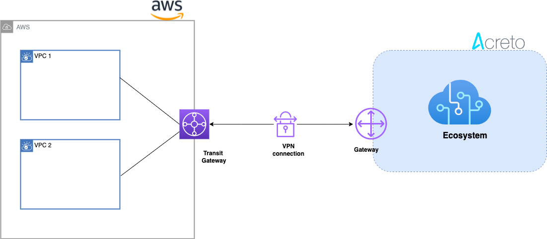
This article describes configuring a Route-Based Site-to-Site IPsec VPN between an Acreto Ecosystem and the Amazon Web Services (AWS) Transit Gateway to access multiple VPCs.
Network Diagram
Concepts and Glossary
- IPsec VPN tunnel: An encrypted link where network traffic can pass between Acreto Ecosystem and AWS VPS.
- Customer gateway: An AWS resource that provides information to AWS about the Acreto IPsec Gateway object.
- Virtual private gateway: The VPN concentrator on the Amazon side of the Site-to-Site VPN connection.
Prerequisites
To setup an IPsec Site-to-Site VPN tunnel between Acreto Ecosystem and AWS VPS, you need:
- Access to Active Acreto Ecosystem
- Access to AWS Management Console
- Pre-configured VPC, subnets, route tables, NACL, and security groups
The Purpose of Site-to-Site IPsec VPN
Acreto, as a Cloud Provider, allows to connect and integrate multiple physical and virtual networks. All connections require stable and secure links. Virtual (EC2) Instances running on Amazon VPC can’t communicate securely with your own (remote) network by default. However, it is possible to connect your network to Acreto Ecosystem. Then, you can enable access to your remote network from your VPC by creating an AWS Site-to-Site VPN (Site-to-Site VPN) connection and configuring routing to pass traffic through the connection.
Acreto Ecosystem configures the routing automatically and passes the traffic between AWS VPC and your network. Additionally, the traffic is scanned by the Acreto Threat Engine to block suspicious traffic and malware.
How To
Use the following procedures to manually set up the AWS Site-to-Site VPN connection transit gateway on Amazon AWS.
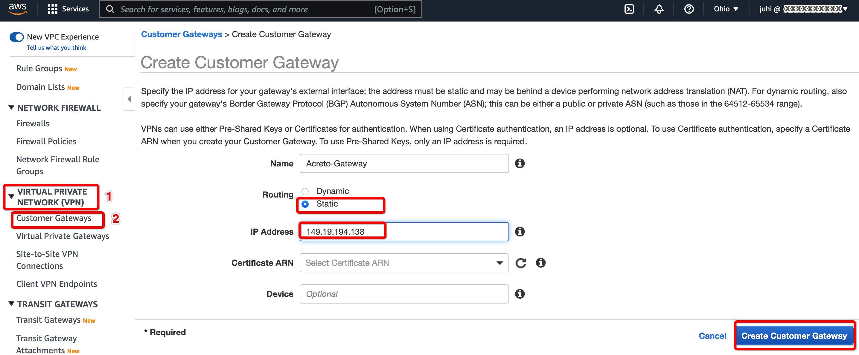
Step 1.1: Create Customer Gateway
Create a new Customer Gateway with Acreto’s public IP.
-
From the VPC Dashboard in the left sidebar, go to VIRTUAL PRIVATE NETWORK (VPN) » Customer Gateways
-
Click Create Customer Gateway
-
Provide the following values :
- Name: Acreto
- Routing: Static
- IP Address: Acreto’s Default Tunnel IP
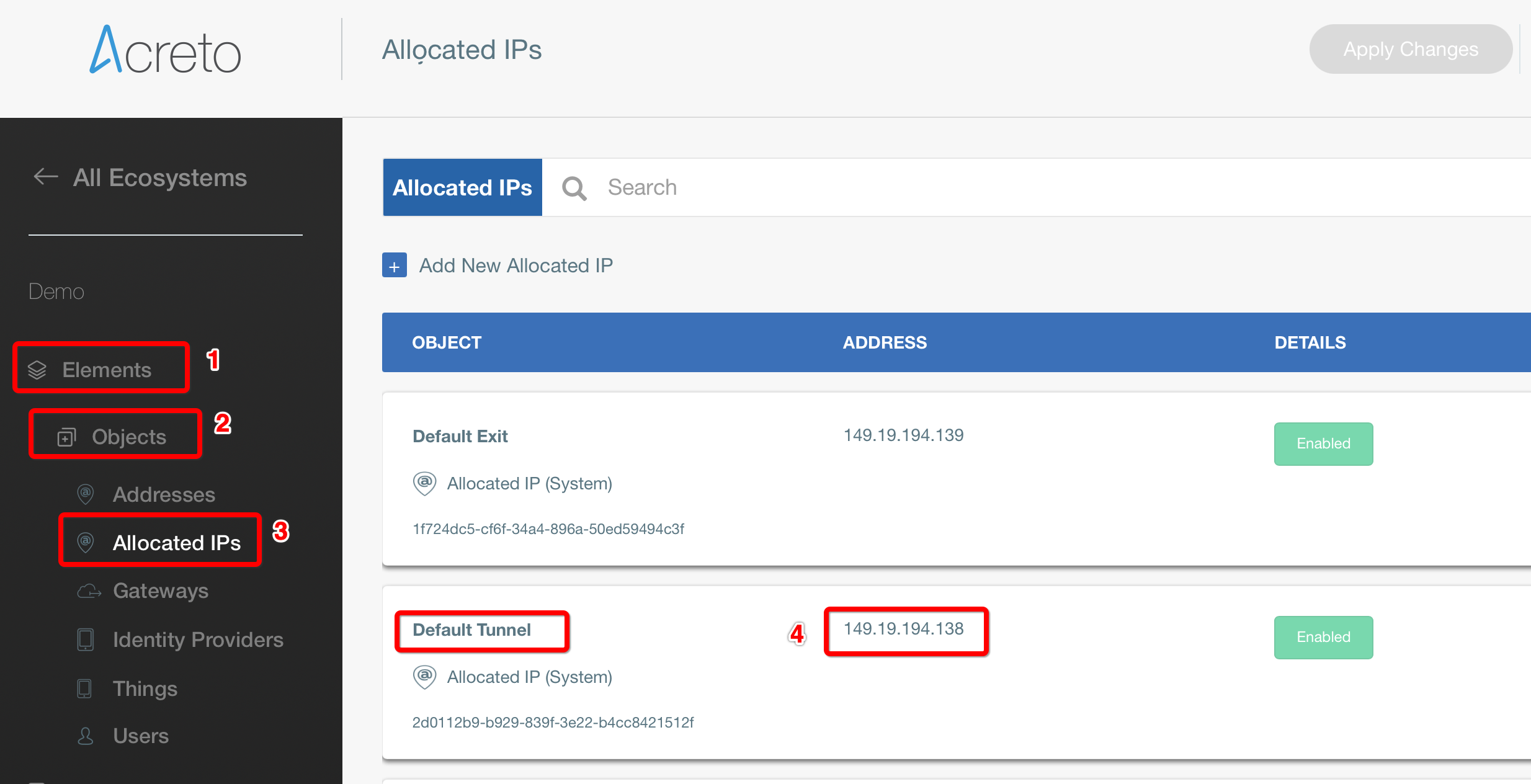
-
Click Create Customer Gateway.
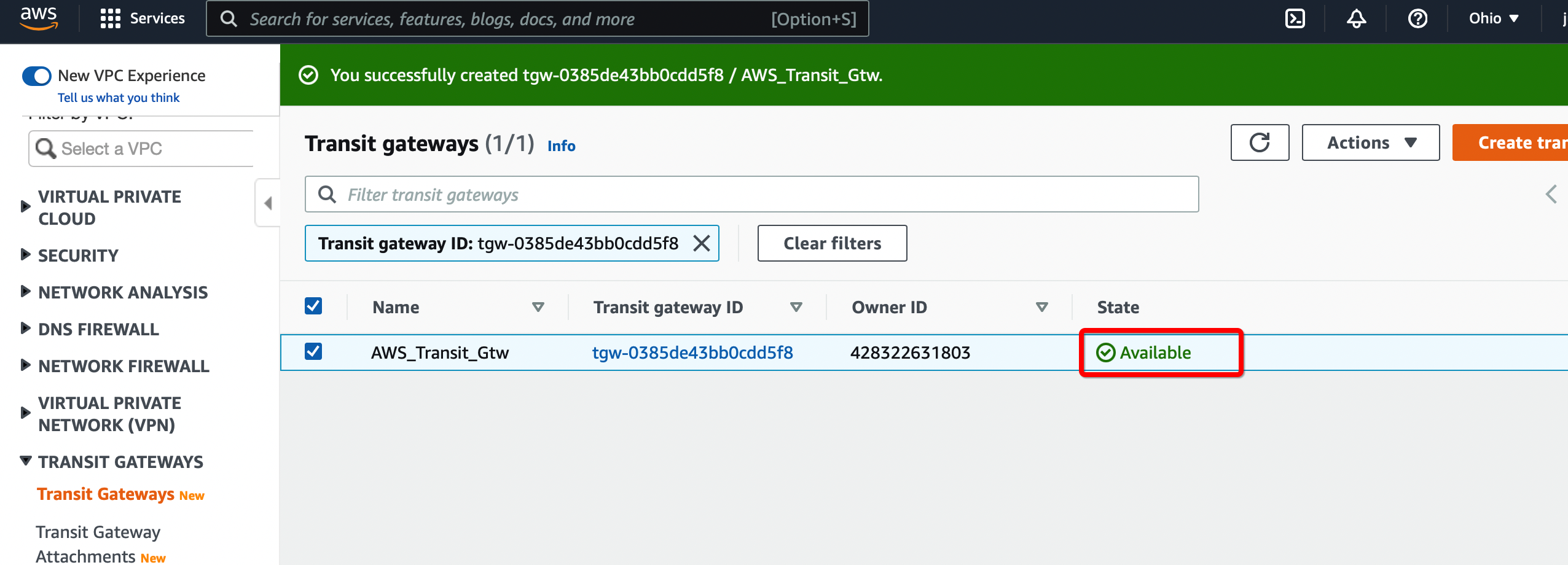
Step 1.2: Create Transit Gateway
Create a Transit gateway that will be used to form the IPsec tunnel with Acreto.
-
From the VPC Dashboard in the left sidebar, go to TRANSIT GATEWAYS » Transit Gateways.
-
Click Create Transit Gateway.
-
Give the name and click Create Transit Gateway

-
Wait for a few minutes to get the state of Transit Gateway to Available.
Step 1.3: Create Transit Gateway attachment
Create a Transit gateway attachment that will attach to the primary VPC.
-
From the VPC Dashboard in the left sidebar, go to TRANSIT GATEWAYS » Transit Gateways Attachment
-
Click Create Transit Gateway Attachment
-
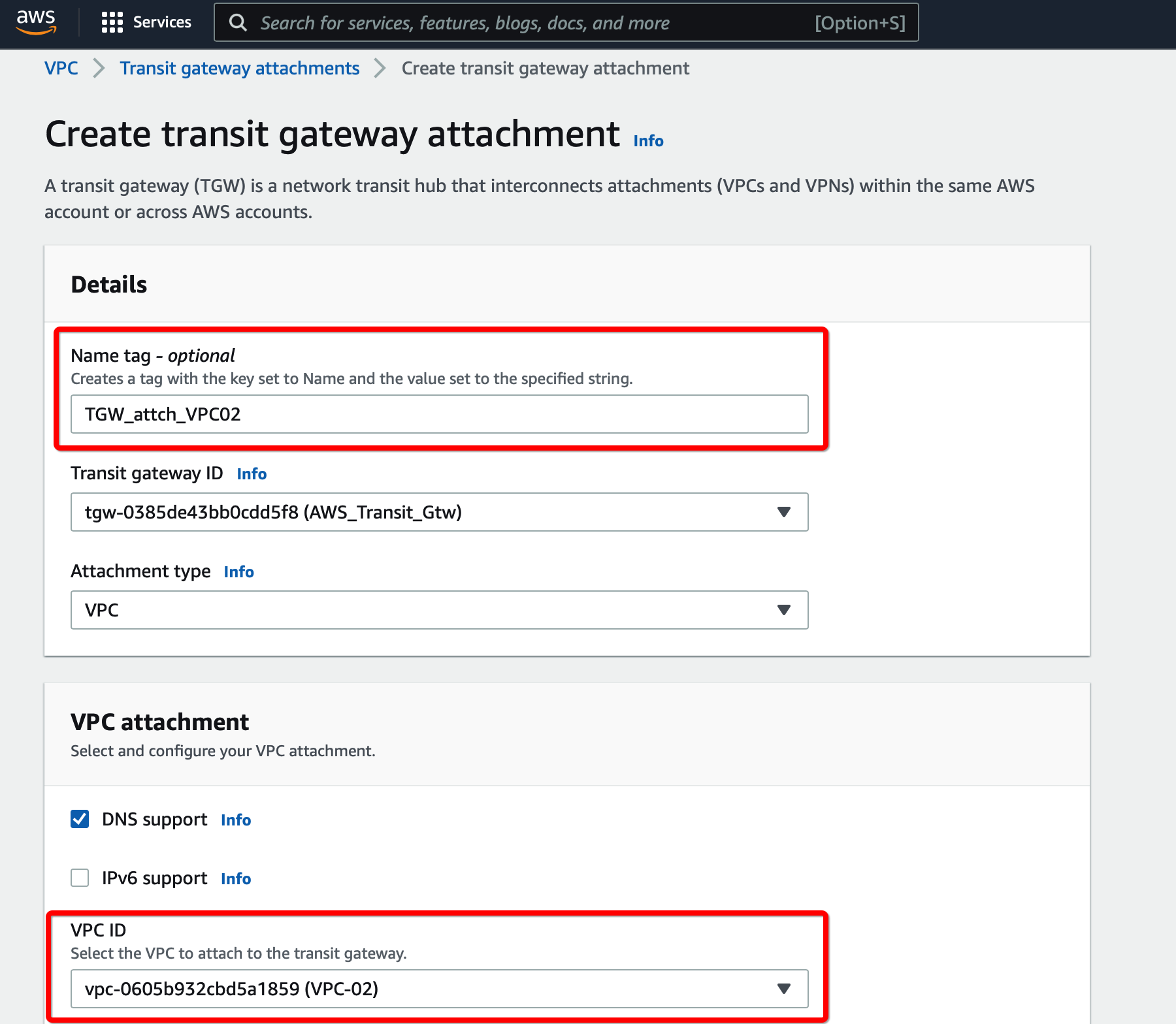
Provide the following values
- Transit Gateway ID - Select the Transit gateway created in the previous step
- Attachment type - VPC
- VPC ID - Select the VPC
- Subnet IDs - Select the subnets that will communicate over the VPN

-
Click Create Transit Gateway attachment
Create a new VPN connection and associate the previously created Virtual Gateway in Step 2 and Customer Gateway in Step 1.
-
From the VPC Dashboard in the left sidebar, go to VIRTUAL PRIVATE NETWORK (VPN) » Site-to-Site VPN Connections.
-
Click Create VPN Connection.
-
Provide the following values in the tunnel setting:
- Name: Acreto_ipsec
- Target Gateway Type: Transit Gateway
- Transit Gateway: Select the Transit gateway created Step 6
- Customer Gateway: Existing
- Customer Gateway ID: Select the Customer gateway created in Step 5
- Routing Options: Static
- Static IP Prefixes: 100.64.0.0/16
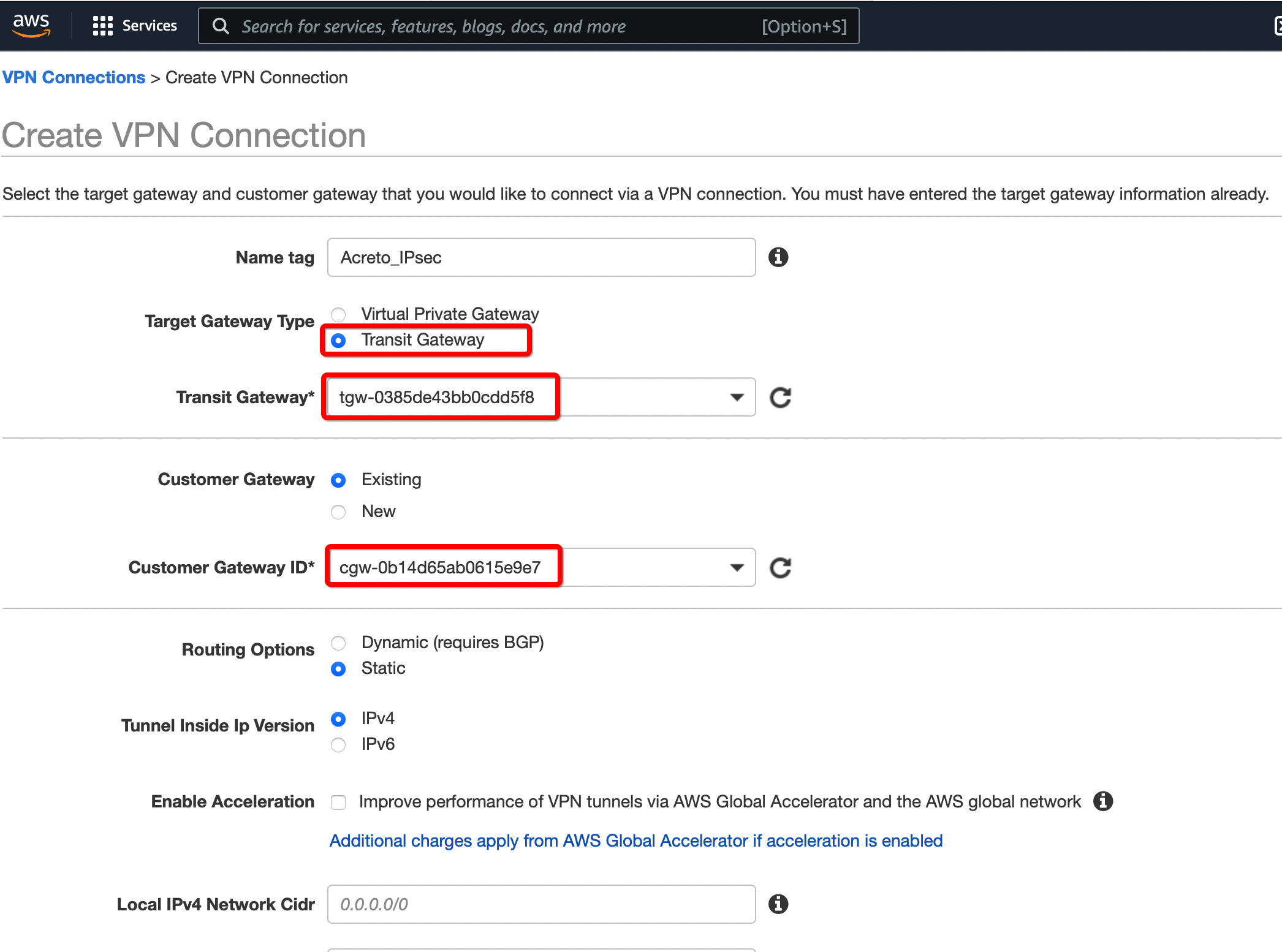
-
Click Create VPN Connection.
-
Select the VPN created and click the tab Tunnel Details. Copy the Outside IP address of the tunnel to form a VPN with Acreto.

This Outside IP address will be used in the next steps to configure the Acreto gateway on Wedge Ecosystem.
Step 1.5: Create Acreto Gateway for IPsec
Create Gateway on Ecosystem by following the instructions in the link. Provide the following values:
- Type: IPsec
- Category: Data Center
- Model: AWS site-to-site VPN
- Connections from: AWS Tunnel’s Outside IP address
- Local network: local_network
- Save and Commit the changes.

Step 1.6: Read the Configuration
-
Click the gateway created on the Wedge.
-
Click the Play button under Configuration Options to generate the strongSwan Config.

-
Once the Config file is generated, click the Download button to download the configuration on the local computer.

-
Unzip the downloaded file and copy the PSK from the file ipsec.secrets

Step 1.7: Update AWS VPN tunnel configuration
-
Goto AWS Site-to-Site VPN connections
-
Select the VPN and click Actions » Modify VPN Tunnel Option

-
Select the tunnel used to create the VPN with Acreto.
-
Update the password copied from the ipsec.secrets file from strongSwan config file downloaded from Wedge

-
In the same window “Modify VPN Tunnel Options” scroll down and select the following action under tunnel configuration:
- DPD Timeout Action: Restart
- Startup Action: Start
-
Click Save
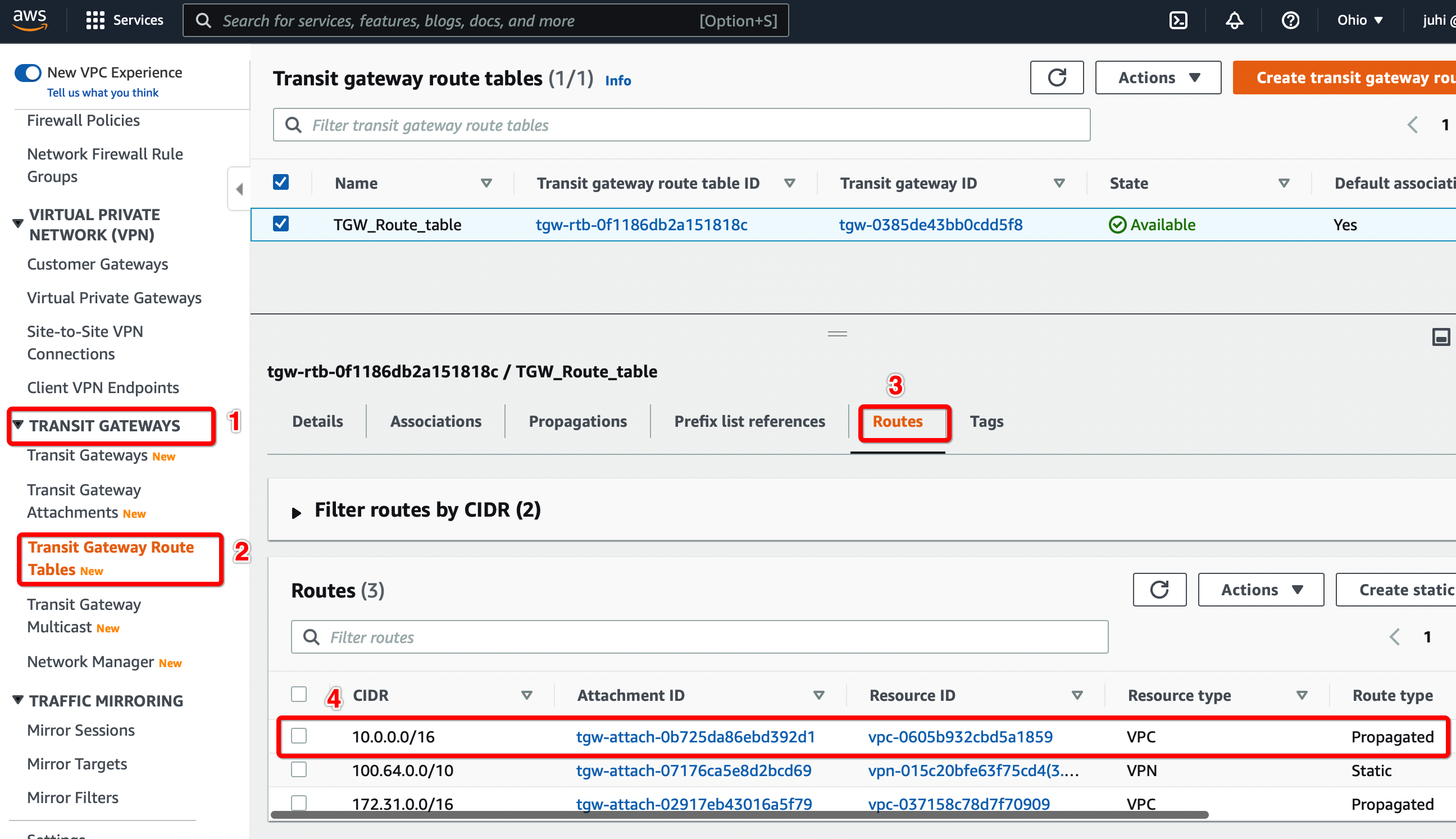
Step 1.8: Update the Transit Gateway Route Table
Configure the Route table to set the default route to the VPN tunnel.
-
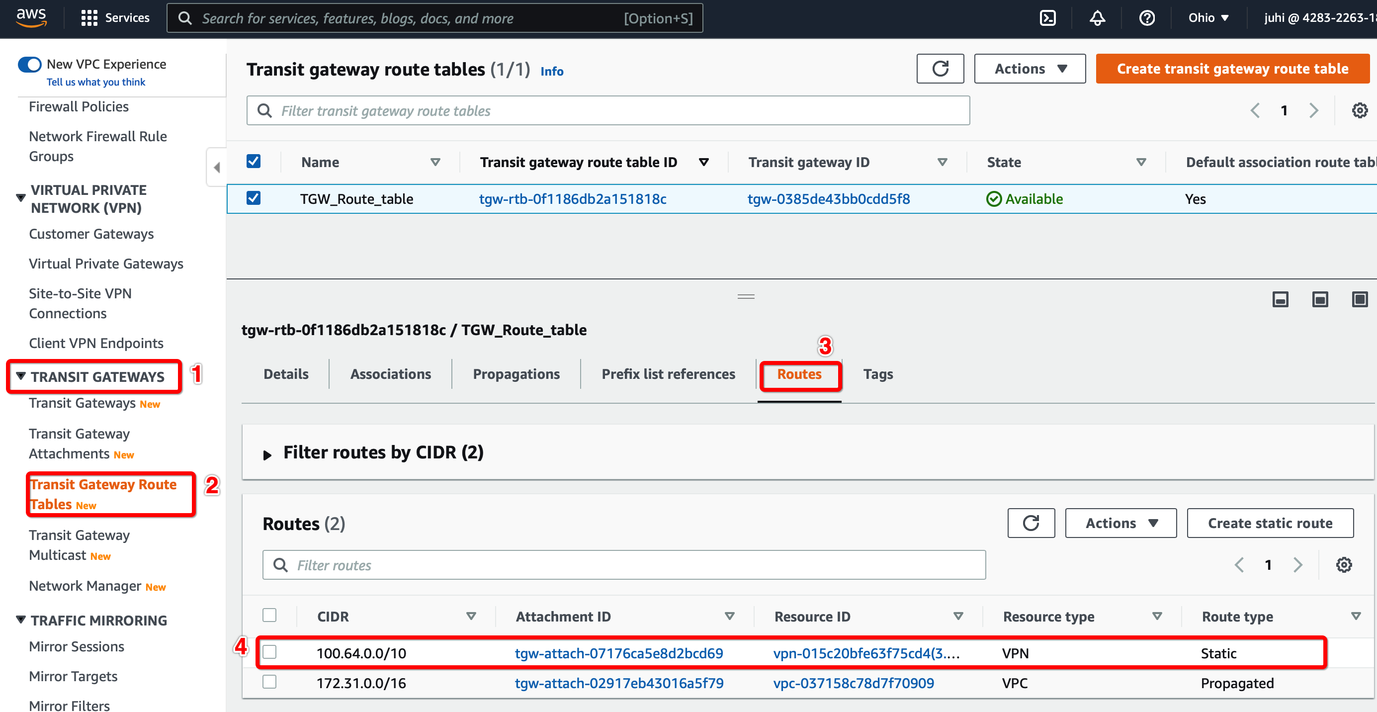
From the VPC Dashboard, click Transit Gateway Route Table under TRANSIT GATEWAYS in the left sidebar
-
Select the Transit gateway Route table entry.
-
Select tab Routes and click Create Static Route
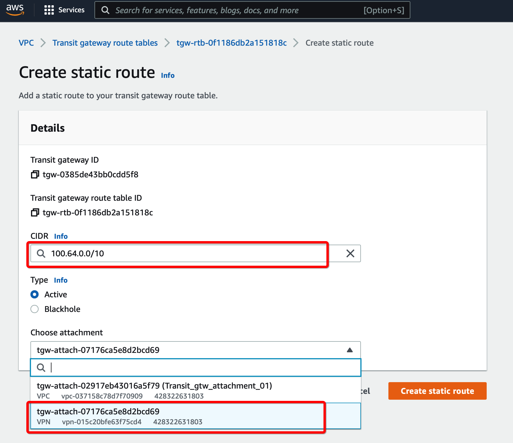
-
Click Create Static Route
Step 1.9: Update Route the Table for the Subnet
-
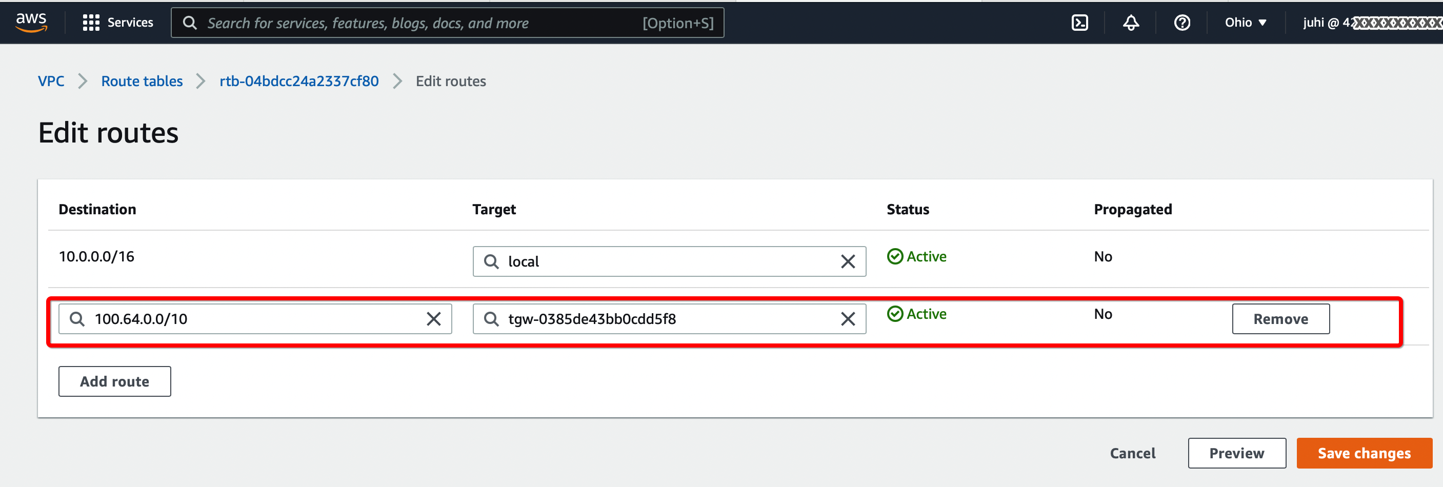
From the VPC Dashboard, click Route Tables under VIRTUAL PRIVATE CLOUD in the left sidebar
-
Select the Route table and click Edit routes. Add the following values :
- CIDR - 100.64.0.0/16
- Attachment - Select the Transit VPN attachment id
-
Click Save changes.
Attach Secondary VPC in the same account to the Transit Gateway
Step 2.1: Create Transit Gateway attachment for Secondary VPC
to TRANSIT GATEWAYS » Transit Gateways Attachment
-
Click Create Transit Gateway Attachment
-
Provide the following values
- Transit Gateway ID - Select the Transit gateway created in step 6
- Attachment type - VPC
- VPC ID - Select the new VPC
- Subnet IDs - Select the subnets that will communicate over the VPN
 .
.
-
Click Create Transit Gateway attachment
Step 2.2: Verify the routes from the new VPC Transit Gateway attachment is available on the Transit Gateway Route table.
Configure Routes from the new VPC transit gateway attachment appears in the Transit Gateway Route table.
-
From the VPC Dashboard, click Transit Gateway Route Table under TRANSIT GATEWAYS in the left sidebar
-
Select the Transit gateway Route table entry.
-
Select tab Routes
-
Check the Static route from the new VPC Transit Gateway attachment is available
Step 2.3: Update the routes for the Subnet in Secondary VPC
Follow Step 1.9 to add the route for Acreto subnet 100.64.0.0/16 through the transit gateway.
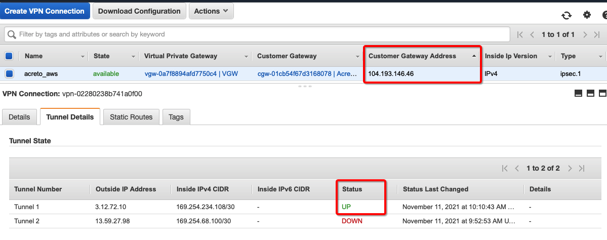
Verify the connections
Once the tunnel connection is successfully established, the status of the connection will be up.
-
To verify on AWS, navigate to the VPN created under VIRTUAL PRIVATE NETWORK (VPN) » Site-to-Site VPN Connections. Verify the following:
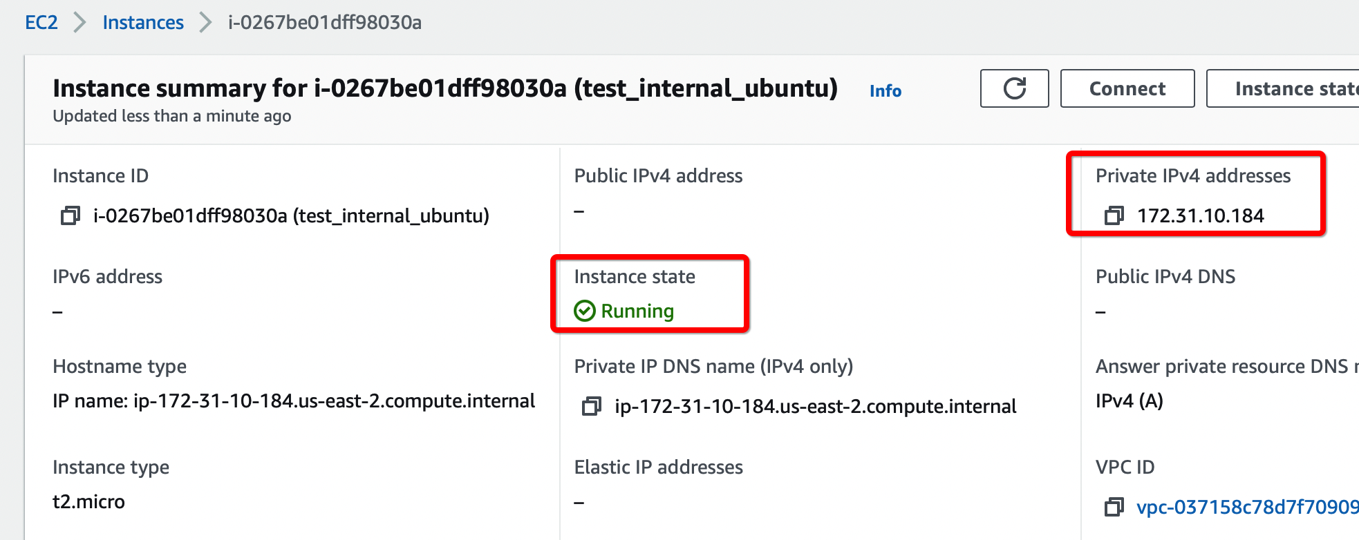
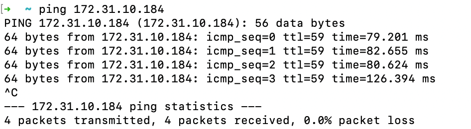
-
Connect a Remote user with the Acreto Connect Client and access the resources in the VPC connected using Transit Gateway.
References and Related Articles
Summary
Acreto Gateway allows setting up an IPsec VPN tunnel with AWS Transit Gateway, which can be used to access resources in multiple VPCs.
Fortinet FortiGate Dual VPN setup
Before You Start
Overview
This article illustrates a Dual VPN setup and explains how to connect the secondary tunnel from your environment to the second Ecosystem which can act as a backup in case of failure of the Primary ISP or Ecosystem. With this setup, when the first tunnel is down, the traffic will automatically start going through the second tunnel to the backup Ecosystem.

Prerequisites
- FortiGate installation
- Ecosystem set up with proper security policies
How-To
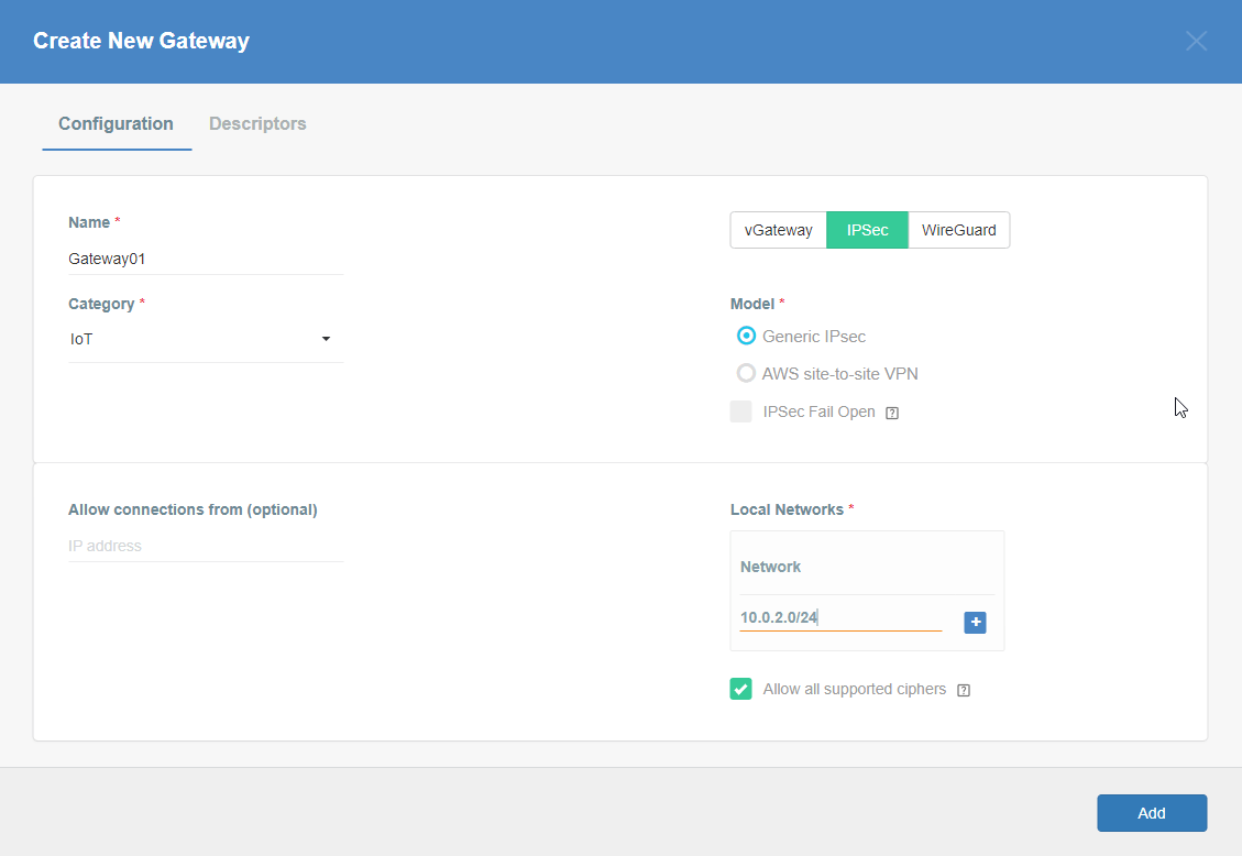
Create Gateway for IPsec
Firstly, you will need to create a new Gateway device in the Acreto platform. Instructions on how to create a new Gateway are available here.
- Name: IPsec connection name must meet the same requirements as the Strongswan connection name (letters and numbers only).
- Category: IoT
- Type: IPsec
- Allow connection from: Empty (describes the source IP address where the IPsec connection will be permitted).
- Local Networks: any local network addresses that will be routed through this gateway.

Info
To simplify testing, add the IP addresses of all interfaces connected to your gateway as Local Networks (you can use /32 prefix for public interface). This will allow you to test connectivity from the gateway through Acreto by using Ping, Traceroute, or similar tools.
Task 1: Read IPsec Gateway Values Required for FortiGate Configuration
To proceed with the FortiGate configuration, you will need a few values from an existing committed Acreto Gateway:
- Gateway Address
- Pre-Shared Key
- Recommended Ciphers
All of these may be found within the Gateway details panel - view the below animation for further instruction.
Animation how to get required values from Gateway [▶]
- In FortiGate, go to VPN > IPsec Tunnels. From Create New drop-down menu, select IPsec Tunnel

- In the next window, give the primary tunnel name and click on Custom and click on Next.

- Configure the following VPN settings:
- IP Version: IPv4
- Remote Gateway: Static IP Address
- IP Address: Primary EcoSystem Gateway
- Interface: Select WAN Interface
- Mode Config: Enable
- DPD Retry interval: 30

- Expand Advance Option and configure as below:
- Add Route: Disabled
- Authentication Method: Pre-shared Key
- Pre-shared Key: enter the pre-shared key
- IKE Version: 2

- In Phase1 Proposal. Delete all proposals except two as below:
- Encryption: AES 128 Authentication: SHA256
- Encryption: AES 128 Authentication: SHA512
- DH Group: 15 , 14, 2
- Key Lifetime: 10800
- Local ID: enter the peer id

- In Phase2 setting, please enter below:
- Encryption: AES 128 Authentication: SHA256
- Encryption: AES 128 Authentication: SHA512
- PFS: Enable
- DH Group: 15 , 14, 2
- Auto Keep Alive: Enable

- Click OK to save the VPN setting.
- Repeat the above steps for the creation of a secondary tunnel. We will use Acreto-ECO-2 as the name of a secondary tunnel in this article.
This step is required for policy routing to work. Any dummy/unused IPs can be used for interfaces.
- Go to Network > Interfaces. Select Acreto-ECO-1 Tunnel interface and click on Edit

- Configure IP as below:
- IP: 169.254.254.1
- Remote IP: 169.254.254.2/32
- Click on Save

- Repeat the step to configure IP on the secondary tunnel interface.
- Go to Network > Interfaces. Select Acreto-ECO-2 Tunnel interface and click on Edit.
- Configure IP as below:
- IP: 169.254.254.3
- Remote IP: 169.254.254.4/32
- Click on Save.

- Go to Network > Static Route. Click on Create New.

- In the next window, configure the static route as below:
- Destination: 0.0.0.0/0
- Interface: Acreto-ECO-1 (Acreato-primary-tunnel)
- Administrative Distance: 30
- Click on Save

- Repeat the step to configure a static route for the secondary tunnel.
- Go to Network > Static Route. Click on Create New.
- In the next window, configure the static route as below:
- Destination: 0.0.0.0/0
- Interface: Acreto-ECO-2 (Acreato-secondary-tunnel)
- Administrative Distance: 30
- Click on Save

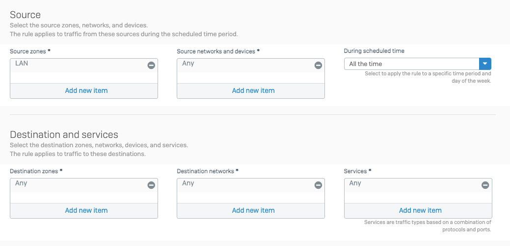
- To configure the policy route, Go to Network > Policy Route. Click on Create New.

- In the next window, configure policy route setting as below:
- Incoming Interface: Select LAN interface
- Source - IP/Netmask: 192.168.253.0/24 (LAN Network)
- Destination - IP/Netmask: 0.0.0.0/0
- Outgoing Interface: Acreto-ECO-1 (Primary Tunnel)
- Gateway Address: 169.254.254.2 (Remote IP for primary tunnel interface)
- Click on save.

- Repeat the step to configure the policy route for the secondary tunnel.
- Go to Network > Policy Route. Click on Create New.
- In the next window, configure policy route setting as below:
- Incoming Interface: Select LAN interface
- Source - IP/Netmask: 192.168.253.0/24 (LAN Network)
- Destination - IP/Netmask: 0.0.0.0/0
- Outgoing Interface: Acreto-ECO-2 (secondary Tunnel)
- Gateway Address: 169.254.254.4 (Remote IP for secondary tunnel interface)
- Click on Save.

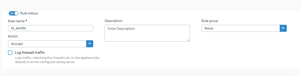
- Go to Policy & Objects > Firewall Policy. Click on Create New.

- In the next window, configure the policy setting as below for primary VPN.
- Name: Give a name to the primary policy
- Incoming Interface: LAN
- Outgoing Interface: Acreto-ECO-1 (Primary Tunnel Interface)
- Source: LAN Address
- Destination: all
- Schedule: Always
- Service: All
- Action: Accept
- NAT: Disable
- Protocol Option: default
- SSL Inspection: no-inspection
- Logging: As needed
- Click on Save.

- Repeat the step to create a firewall policy to allow traffic on secondary VPN.
- Go to Policy & Objects > Firewall Policy. Click on Create New.
- Name: Give a name to the secondary policy
- Incoming Interface: LAN
- Outgoing Interface: Acreto-ECO-2 (Secondary Tunnel Interface)
- Source: LAN Address
- Destination: all
- Schedule: Always
- Service: All
- Action: Accept
- NAT: Disable
- Protocol Option: default
- SSL Inspection: no-inspection
- Logging: As needed
- Click on Save.

Task 8. Check the status of the VPN.
- Go to Dashboard > Network > IPsec.
- If the tunnel is showing down. Select the tunnel and click on Bring UP

- Primary and secondary VPN selection is handled by Policy Route.
Traffic will be matched with the policy on top if both tunnels are up.

Summary
After this setup, there are two tunnels created from FortiGate to Acreto Primary and Secondary Ecosystem through Primary and Secondary tunnel respectively. If the primary tunnel goes down, all traffic will start going from the backup tunnel, which in this case is the Secondary tunnel.
Fortinet FortiGate IPsec Configuration
Prerequisites
- FortiGate installation
- Ecosystem set up with proper security policies
Create Gateway for IPsec
Firstly, you will need to create a new Gateway device in the Acreto platform. Instructions on how to create a new Gateway are available here.
- Name: IPsec connection name must meet the same requirements as the Strongswan connection name (letters and numbers only).
- Category: IoT
- Type: IPsec
- Allow connection from: Empty (describes the source IP address where the IPsec connection will be permitted).
- Local Networks: any local network addresses that will be routed through this gateway.
Info
To simplify testing, add the IP addresses of all interfaces connected to your gateway as Local Networks (you can use /32 prefix for public interface). This will allow you to test connectivity from the gateway through Acreto by using Ping, Traceroute, or similar tools.
How-To
Step 1: Read IPsec Gateway Values Required for FortiGate Configuration
To proceed with the FortiGate configuration, you will need a few values from an existing committed Acreto Gateway:
- Gateway Address
- Pre-Shared Key
- Recommended Ciphers
All of these may be found within the Gateway details panel - view the below animation for further instruction.
Animation how to get required values from Gateway [▶]
Use VPN Wizard to create all basic configurations.
- Log in to the FortiGate Dashboard.
- In the navigation panel, select VPN > IPsec Wizard and view VPN Creation Wizard

- Complete the first step of VPN Wizard, VPN Setup, by inserting these values:
- Name: AcretoGate (or your own readable name)
- Template Type: Site to Site
- Remote Device Type: Cisco
- NAT Configuration: No NAT between sites
- When the form is ready, click Next.
- Complete the second step of the VPN wizard, Authentication.
- Remote Device: IP address
- IP Address: Input the IP address of your Acreto Gateway created in Wedge.
- Outgoing Interface: Select the existing interface that will be used for this connection.
- Authentication Method: Pre-shared Key
- Pre-shared Key: Enter the Pre-shared Key common for Acreto and FortiGate (available on Acreto Wedge in the Gate configuration panel).
- When the form is ready, click Next.
- Complete the last step of the VPN wizard, Policy & Routing.
- Local Interface: Select the local interface that will use this connection.
- Local Subnets: Define local subnets for this connection.
- Remote Subnets: Define remote (Acreto site) subnets for this connection (0.0.0.0/0 - for all networks).
- Internet Access: None
- Click on Save.
- From the side menu, choose VPN > IPsec Tunnels to confirm that the newly created VPN is displayed on the list in the Site to Site section.

- From the side menu, choose VPN > IPsec Tunnels. You should see the Acreto Gate tunnel created in the previous step.
- Double-Click on the tunnel name to open editing options.
- On the Edit VPN tunnel screen, click Convert To Custom Tunnel- this action will convert your VPN to a custom tunnel, allowing you to configure additional settings.

- After you click on Convert To Custom Tunnel, a few additional options will be displayed on the screen.
- Edit Network by clicking on Edit and set the Mode Config to check, as shown on the screen below (IP address and Interface will be different).

- Edit Authentication by clicking on Edit and set Version to 2, as shown on the screen below.

- Edit Phase 1 Proposal by clicking on Edit and set Version to 2, as shown on the screen below.
- Encryption: AES256
- Authentication: SHA512
- Diffie-Hellman Group: 16
- Key Lifetime: 3600

- Edit Phase 2 Selectors by clicking on Edit > Advanced, as shown on the screen below:
- Encryption: AES256
- Authentication: SHA512
- Enable Replay Detection: check
- Enable Perfect Forward Secrecy (PFS): check
- Diffie-Hellman Group: 16
- Autokey Keep Alive: check
- Key Lifetime: Seconds
- Seconds: 3600

- When all edits are complete, click OK at the bottom of the screen to convert the tunnel. From now on, the IPsec tunnels panel will show as Custom.
- From the side menu, choose Network > Interfaces. Find the tunnel interface name AcretoGate under WAN interface.
- Edit the interface and assign local and remote IP. You can choose any IP, it will not affect the traffic.
- IP: <any /32 IP>
- Netmask: 255.255.255.255
- Remote IP/Netmask: <any /32 IP>

- From the side menu, choose Network > Static Routes. Find the static route created by the wizard. Should be with the name
<Tunnel_name>_remote.
- Edit the static route and change the Administrative Distance to 50.

- Click OK to save the route.
- From the side menu choose Network > Policy Routes and click on Create New
- Configure the new Policy Route, as shown on the screen below.
- Incoming Interface: <select your local interface>
- Source Address-Ip/Netmask : <enter local subnet >
- Destination Address-Ip/Netmask : 0.0.0.0/0
- Action : Forward Traffic
- Outgoing Interface : AcretoGate OR <choose your tunnel interface>
- Gateway Address : <enter Remote IP configured in Step 4.2.3>

- Click OK to Save
- From the side menu, choose Dashboard > Network > IPsec
- Select the Tunnel and click on Bring Up.
When the configuration is complete, all network traffic on the selected interface and the selected subnet(s) is redirected through Acreto.
Fortinet FortiGate IPsec Configuration through CLI
Before you start
Overview
This article will show you how to use CLI to connect the FortiGate managed network to the Acreto Ecosystem.
Prerequisites
- FortiGate installation
- Ecosystem set up with proper security policies
How-To
Create Gateway for IPsec
This step is optional, skip it if you already own the Gateway.
Firstly, you will need to create a new Gateway device in the Acreto
platform. Instructions on how to create a new Gateway are available
here.
- Name: IPsec connection name must meet the same requirements as the Strongswan connection name (letters and numbers only).
- Category: IoT
- Type: IPsec
- Allow connection from: Empty (describes the source IP address
where the IPsec connection will be permitted).
- Local Networks: any local network addresses that will be routed
through this gateway.
Info
To simplify testing, add the IP addresses of all
interfaces connected to your gateway as Local Networks (you can use /32
prefix for public interface). This will allow you to test connectivity
from the gateway through Acreto by using Ping, Traceroute, or similar
tools.
Step 1: Read IPsec Gateway Values Required for Fortigate Configuration
To proceed with the Fortigate configuration, you will need a few values
from an existing committed Acreto Gateway:
- Gateway Address
- Pre-Shared Key
- Recommended Ciphers
All of these may be found within the Gateway details panel - view the
below animation for further instruction.
Animation how to get required values from Gateway [▶]
Use the following commands to create a VPN through CLI.
Log in to the Fortigate CLI.
-
Configure IPsec VPN Phase-1
config vpn ipsec phase1-interface
edit AcretoGate
 set interface <wan_interface>
 set peertype any
 set net-device disable
 set mode-cfg enable
 set proposal aes128-sha256 aes256-sha512
 set ike-version 2
 set keylife 10800
 set remote-gw acreto-peer-ip       (Copy from Wedge Dashboard)
 set psksecret psk                  (Copy from Wedge Dashboard)
 set dhgrp 16
 set localid local-id              (Copy from Wedge Dashboard)
 next
end
-
Configure IPsec VPN Phase-2
config vpn ipsec phase2-interface
 edit AcretoGate
  set phase1name AcretoGate
  set proposal aes256-sha512 aes256gcm
  set dhgrp 16
  set keepalive enable
  set keylifeseconds 3600
 next
end
-
Create addresses for all local addresses/subnets
config firewall address

edit AcretoGate_local_1
  set allow-routing enable
  set subnet 192.168.1.0 255.255.255.0
  next

edit AcretoGate_local_2
  set allow-routing enable
  set subnet 192.168.2.0 255.255.255.0
  next
end
-
Create an address group to add all the addresses created in the previous step
config firewall addrgrp

edit AcretoGate_local_grp
 set member AcretoGate_local_1 AcretoGate_local_2
 next
end
-
Outbound Policy for traffic originating from Local lan interface to internet through Acreto VPN
config firewall policy
edit 0
  set name Outbound_toAcreto
  set srcintf lan_interface_ip
  set dstintf AcretoGate
  set srcaddr AcretoGate_local_grp
  set dstaddr all
  set action accept
  set schedule always
  set service ALL
  next
end
-
Inbound Policy for traffic coming from Acreto VPN to Local lan
config firewall policy
edit 0
  set name Inbound_fromAcreto
  set srcintf AcretoGate
  set dstintf  lan_interface_ip
  set srcaddr all
  set dstaddr AcretoGate_local_grp
  set action accept
  set schedule always
  set service ALL
  next
end
Scenario 1: When traffic from all local subnet/interfaces need to pass through the tunnel
-
Add Static Route
config router static
edit 0
 set dst Acreto_PeerIP
 set device wan_interface
 Set gateway ISP_Gateway
 next
edit 0
 set dst 0.0.0.0 0.0.0.0
 set device AcretoGate
 set distance 4
 next
end
Scenario 2: When traffic from a specific subnet/interface needs to pass through the tunnel.
-
Add IP at the tunnel interface
config system interface
edit "AcretoGate"
 set ip 2.2.2.2 255.255.255.255
 set remote-ip 2.2.2.3 255.255.255.255
 next
end
-
Add Static Route to direct the traffic through the tunnel with a higher administrative distance
config router static
edit 0
 set distance 254
 set device AcretoGate
 set dst 0.0.0.0 0.0.0.0
 next
end
-
Add Policy Route to direct the specific traffic through the tunnel
config router policy
edit 0
 set input-device lan_interface
 set srcaddr AcretoGate_local_grp
 set dstaddr all
 set output-device AcretoGate
 Set gateway 2.2.2.3
 next
end
Run the following command to bring the tunnel up bash diagnose vpn tunnel up AcretoGate
diagnose vpn tunnel up AcretoGate
- Check the status of tunnel Phase-1
diagnose vpn ike gateway list name AcretoGate
diagnose vpn tunnel list name AcretoGate
Summary
Once the VPN connection is successfully established, all the internet traffic will be routed through Acreto.
Linux - Automatic IPsec Configuration
Prerequisites
- Ubuntu 18.04 or newer installed on your device
- Ecosystem set up with proper security policies
Create Gateway for IPsec
If you didn’t do it yet, you need to create a new Gateway device on the Acreto
platform.
-
Login to the Acreto platform at wedge.acreto.net
-
Select your ecosystem and go to Objects using the left menu.
-
Click Add new Object and select Gateway.
-
Fill at least:
-
Name: the name of the IPSec connection needs to be compatible with
Strongswan connection name requirements (basically, only letters and
numbers)
-
Category: IoT
-
Allow connection from: Empty (describes the source IP address where the
IPsec connection will be permitted)
-
Local Networks: - your local network addresses that should be routed
through this gateway
Note: To simplify testing, add IP addresses of all interfaces connected to your gateway as Local Networks (you can use /32 prefix for public interface). This will allow testing connectivity from the gateway through Acreto using ping, traceroute, and similar tools.
-
Save the created Gateway by pressing Add.
-
Add a security policy that will allow communication from the Gateway device to the Internet.

-
Commit pending changes (top of the screen)
 Note: to successfully test your connectivity, you also need to create a
security policy that will allow traffic going through your device.
Note: to successfully test your connectivity, you also need to create a
security policy that will allow traffic going through your device.
Generate Strongswan config files
-
Log in to the Acreto platform at
wedge.acreto.net
-
Select your ecosystem and go to Objects using the left menu
-
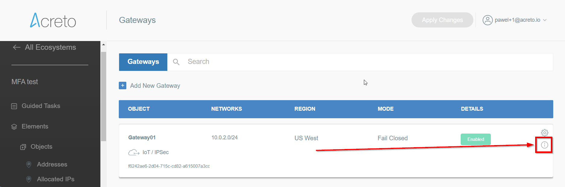
Open the gateway object which you want to use by clicking on its “Info” button.
-
Generate the IPsec strongSwan config using Configuration Options >
Bare Metal, OS and Software
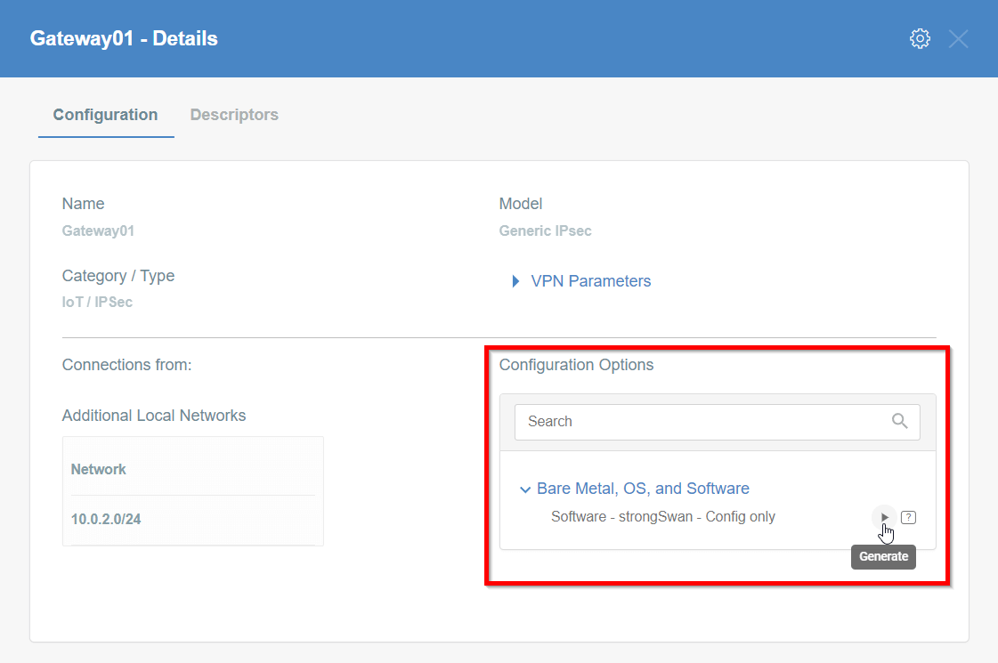
Then Click on [Play Button]
-
Copy the link to the IPsec strongSwan config file
Installation using acreto-ipsec.sh script
-
Execute the following commands on your Linux shell
curl -fsSL https://kb.acreto.net/reference-material/downloads/acreto-ipsec.sh | sudo bash -s -- [URL_to_strongswan_config]
where [URL_to_strongswan_config] is the URL copied in previous step.
Example:
curl -fsSL https://kb.acreto.net/reference-material/downloads/acreto-ipsec.sh | sudo bash -s -- https://api-is-rock-solid.acreto.net/v2/gateways/ipsec/config/strongswan?_token=s.WNJJeTxWsIeXMkgeIA96SOe8
IPsec tunnel and routing verification
-
Ensure that traffic goes through Acreto (with traceroute or mtr)
Execute the command:
The ouput should indicate that packets go through 100.65.0.x:
Host                     Loss%   Snt   Last   Avg  Best  Wrst StDev
1. 100.65.0.30            0.0%     9  225.1 225.1 224.6 225.8   0.3
2. 100.65.0.1             0.0%     8  225.9 227.5 225.7 237.1   3.9
3. ???
4. nyk-b2-link.telia.net  0.0%     8  226.0 226.9 226.0 228.3   0.7
5. 72.14.218.254          0.0%     8  227.1 227.8 226.4 230.4   1.2
6. 108.170.248.97         0.0%     8  227.1 227.2 226.8 227.9   0.4
7. 108.170.227.211        0.0%     8  226.5 226.9 226.0 227.7   0.6
8. dns.google             0.0%     8  226.7 227.6 226.7 229.2   0.8
IPsec Operational Commands
-
Restart IPsec service with the following command: ipsec restart
-
Wait approximately 10 seconds, and check the status of IPsec: ipsec statusall
-
If the connection did not start, try to take it up manually:
CONN=`grep '^conn .*' /etc/ipsec.d/*.conf|cut -d' ' -f2`; echo $CONN
ipsec up $CONN
It should display information useful for debugging purposes.
-
Ensure everything works fine with:
ipsec statusall
ip address show
ip route show
-
Check if you have Internet access
IPsec Watchdog
In case you Internet connection if very unstable or your ISP changes your public IP, then you may consider running an IPsec watchdog that verifies every minute if the tunnel is passing the traffic to Acreto Ecosystem.
Please download the script and follow the steps from the comments section at the beginning of this script.
Click on the button and save the script in your home directory:
Get ipsec-watchdog.sh
or open the terminal and download the script directly to your vGateway using the command:
cd /etc/ipsec.d/
wget https://kb.acreto.net/reference-material/downloads/ipsec-watchdog.sh
Linux - Manual IPsec Configuration
Prerequisites
- Ubuntu 18.04 or newer installed on your device
- Ecosystem set up with proper security policies
Create Gateway for IPsec
If you didn’t do it yet, you need to create a new Gateway device on the Acreto
platform.
-
Log in to the Acreto platform at wedge.acreto.net
-
Select your ecosystem and go to Objects using the left menu.
-
Click Add new Object and select Gateway.
-
Fill at least:
-
Name: - the name of IPSec connection, needs to be compatible with
Strongswan connection name requirements (basically, only letters and
numbers)
-
Category: IoT
-
Allow connection from: Empty (describes the source IP address where the
IPsec connection will be permitted)
-
Local Networks: - your local network addresses that should be routed
through this gateway
Note: To simplify testing, add IP addresses of all interfaces connected to your gateway as Local Networks (you can use /32 prefix for public interface). This will allow testing connectivity from the gateway through Acreto using ping, traceroute, and similar tools.
-
Save the created Gateway by pressing Add.
-
Add security policy that will allow communication from the Gateway device to the Internet.

-
Commit pending changes (top of the screen)
Note: to successfully test your connectivity, you also need to create a
security policy that will allow traffic going through your device.
Generate Strongswan config files
-
Log in to the Acreto platform at
wedge.acreto.net
-
Select your ecosystem and go to Objects using the left menu
-
Open the gateway object which you want to use by clicking on its “Info” button.

-
Download Strongswan configuration using Configuration Options >
Software Clients with Config

-
Download Strongswan configuration to your device.
Install dependencies on the device
-
Log in to your device.
-
Set up time/date server, to do that use the following command:
sudo timedatectl set-ntp on
ntpdate -s ntp.ubuntu.com
-
Install required packages:
sudo apt-get update
sudo apt-get install -y --no-install-recommends \
    apt-utils \
    ifupdown2 \
    inetutils-ping \
    strongswan \
    kmod \
    openssl \
    libstrongswan-standard-plugins
Apply configuration files
-
Log in to your device.
-
Unzip downloaded config file and copy respective files to their location:
unzip -x 10b6c4d8-0e9a-f5c7-c4c9-7edd6a6493ed.zip
sudo cp -r etc/*  /etc
-
Ensure the files are in proper location
/etc/ipsec.d/[connection uuid].conf/etc/ipsec.d/leftifupdown.sh/etc/ipsec.secrets
Enable gateway mode (optional)
To work in gateway mode, you need to configure IPsec to use VTI devices.
Modify /etc/strongswan.d/charon.conf - leave all on defaults except for the
following:
install_routes = no
install_virtual_ip = no
ignore_routing_tables = 220
Modify connection file /etc/ipsec.d/*.conf to enable VTI support -
uncomment mark and leftupdown options:
# uncomment this line for policy routing configuration
mark=105

# uncomment this line for policy routing configuration
leftupdown=/etc/ipsec-leftupdown.sh
Determine connection name as defined in ipsec configuration:
CONN=`grep '^conn .*' /etc/ipsec.d/*.conf|cut -d' ' -f2`; echo $CONN
Create a routing file that will contain (remote) networks which should be
routed through the Acreto platform - by default, it would be a default gateway:
cat > /etc/ipsec.d/$CONN.route << EOF
0.0.0.0/0
EOF
Enable IP forwarding
echo net.ipv4.ip_forward=1 > /etc/sysctl.d/10_ac_ip_forward.conf
systemctl restart systemd-sysctl
sed -i'' -e s/auto=route/auto=start/ /etc/ipsec.d/*.conf
Start IPSec
-
Restart ipsec service with following command:
-
Wait approximately 10 seconds, and check status of ipsec:
-
If the connection did not start, try to take it up manually:
CONN=`grep '^conn .*' /etc/ipsec.d/*.conf|cut -d' ' -f2`; echo $CONN
ipsec up $CONN
It should display information useful for debugging purposes.
-
Ensure everything works fine with:
ipsec statusall
ip address show
ip route show
Check if you have Internet access enabled.
-
Check if you have Internet access enabled.
Validation
Ensure that traffic goes through our platform (with traceroute, mtr,). Verify
with the command below
Tunnel verification command
Expected output after successful tunnel creation
Host                     Loss%   Snt   Last   Avg  Best  Wrst StDev
1. 100.65.0.30            0.0%     9  225.1 225.1 224.6 225.8   0.3
2. 100.65.0.1             0.0%     8  225.9 227.5 225.7 237.1   3.9
3. ???
4. nyk-b2-link.telia.net  0.0%     8  226.0 226.9 226.0 228.3   0.7
5. 72.14.218.254          0.0%     8  227.1 227.8 226.4 230.4   1.2
6. 108.170.248.97         0.0%     8  227.1 227.2 226.8 227.9   0.4
7. 108.170.227.211        0.0%     8  226.5 226.9 226.0 227.7   0.6
8. dns.google             0.0%     8  226.7 227.6 226.7 229.2   0.8
Palo Alto Networks IPsec Configuration
This section describes how to configure two IPSec VPN tunnels on a PA-200 firewall running version 9.1.x. Refer to Palo Alto Networks documentation for additional information about the web interface.
IPSec Connectivity Guide for Palo Alto Networks Firewall
The ethernet1/2 interface is connected to the internal corporate network. This interface will act as a gateway to the internal corporate network. The ethernet1/1 interface is the external interface. The internal network configuration will be in a trust security zone, and the external network interface configuration will be in an untrust security zone. Also, ensure that both interfaces use the same Virtual Router service.

To configure the IPSec VPN tunnels on PA-200, complete the following tasks:
Task 1: Create a New Virtual Router
For this task, you will create a new Virtual Router. To configure the new Virtual Router:
- In the Palo Alto Networks web interface, go to Network → Virtual Routers.
- Click Add to add a new Virtual Router.
- Enter the Virtual Router name, in this case vrouter.
- Click OK to save the vRouter configurations.
Show image
Task 2: Create New Zones
It is recommended to use separate zones to setup IPsec tunnels with PAN.
To configure trust and untrust zones, execute the following commands:
- In the Palo Alto Networks web interface, go to Network → Zones.
- Click Add to create a new zone.
- Enter the trust zone name, in this case trust. Choose zone type Layer3.
Show image
- Click OK to save the zone.
- Click Add to create a new zone.
- Enter the untrust zone name, in this case untrust. Choose zone type Layer3.
Show image
- Click OK to save the zone.
Task 3: Configuring the External Ethernet Interface
Configure the external network interface on PAN to be an untrust zone.
- In the Palo Alto Networks web interface, go to Network -> Interfaces
- Navigate to the Ethernet tab and click on Ethernet 1/1
- Set the Interface Type to Layer3
- Configure the ethernet 1/1, assign it to an untrust zone and connect to vrouter Virtual Router
Show image
- Configure the IP address on the external network, in this example 10.1.203.96/24
Show image
- Click OK to save the configurations
Task 4: Configuring the Internal Ethernet Interface
Configure the internal network interface on PAN to be a trust zone.
- In the Palo Alto Networks web interface, go to Network -> Interfaces.
- Navigate to the Ethernet tab and click on Ethernet 1/2.
- Set the Interface Type to Layer3.
- Configure the ethernet 1/2, assign it to a trust zone and connect to vrouter Virtual Router.
Show image
- Configure the IP address on the internal interface, in this case 10.1.201.96/24.
Show image
- Click OK to save the configurations.
Task 5: Configuring the Tunnel Interfaces
Configure the tunnel interface on the external interface (ethernet1/1). Ensure the tunnel is configured in the untrust security zone. In this example, the tunnel interface is named tunnel.1 with a source IP address 10.1.203.93.
To configure the primary tunnel interface:
- In the Palo Alto Networks web interface, go to Network -> Interfaces.
- Click the Tunnel tab.
- Click Add to create a new tunnel interface.
- In the Tunnel Interface window, complete the following:
Show image
- Interface Name: Enter a name for the tunnel interface, such as tunnel.1.
- Netflow Profile: Choose the appropriate NetFlow profile. In this example, it’s None.
- Comment: Enter additional notes or information (optional).
- Assign Interface To:
- Virtual Router: Choose vrouter.
- Security Zone: Choose untrust.
- Under the IPv4 tab, assign IP address 10.1.203.93 to the tunnel.1 interface.
Show image
- Click OK to save the tunnel interface.
- Click *Commit to apply the configurations.
Task 6: Creating the IKE Crypto Profile
Create an IKE crypto profile that specifies the security settings for the IKE phase 1 negotiations.
To create an IKE crypto profile:
- In the Palo Alto Networks web interface, go to Network.
- Expand Network Profiles.
- Select IKE Crypto.
- Click Add to create an IKE crypto profile.
- In the IKE Crypto Profile window, complete the following:
- Name: Enter a name for the IKE crypto profile. In this case: acreto-ike-crypto.
- DH Group: Click Add and choose group14, group19, group20.
- Encryption: Click Add and choose aes-128-cbc aes-256-cbc.
- Authentication: Click Add and choose sha256, sha384, sha512.
- Lifetime: Set it to 8 hours.
Show image
- Click OK to save configurations.
Task 7: Creating the IKE Gateway
Create IKE gateways using the Acreto Gateway IP address. In this case: 104.193.146.132.
To create the primary IKE gateway:
- In the Palo Alto Networks web interface, go to Network.
- Expand Network Profiles.
- Click IKE Gateways.
- Click Add.
- In the IKE Gateway window, complete the following:
- Name: Enter a name for the IKE gateway, such as Acreto-IPsec.
- Version: Select IKEv2 only mode.
- Interface: Choose the external interface ethernet 1/1.
- Local IP Address: Choose None.
- Peer IP Type: Choose Static.
- Peer IP Address: Enter the Acreto Gateway address for the primary gateway. In this case, it's 104.193.146.132.
- Pre-shared Key: Enter the pre-shared key you generated in the Acreto web Portal.
- Confirm Pre-shared Key: Reenter the pre-shared key.
- Local Identification: Enter the Peer ID from the Acreto Web Portal.
- Peer Identification: Choose None.
- Show Advanced Phase 1 Options: Select to show the following options.
- IKE Crypto Profile: Choose the IKE crypto profile you created in the previous step. In this case, it's acreto-ike-crypto.
- Enable Passive Mode: Deselect.
- Enable NAT Traversal: Select.
- Liveness Check: Deselect.
- Below are reference snapshots of the IKE gateway configurations.
Show image
Show image
- Click OK to save configurations.
Note: To view the Acreto Web Portal information, complete the following steps:
- Log in to https://wedge.acreto.net/.
- Click on the Ecosystem you want to connect to.
- Navigate to Elements → Objects → Gateways.
- Navigate to the gateway you want to connect to and click the Information sign on the right.
Show image
- A new window will appear. Click on “VPN Parameters” to expand the details:
Show image
- From here you can view the Pre-Shared Key, Gateway Address and Peer ID.
- These parameters will be used for Task #7.
Task 8: Creating the IPSec Crypto Profile
Create an IPSec crypto profile that specifies the security parameters for the IKE phase 2 negotiations.
To create an IPSec crypto profile:
- In the Palo Alto Networks web interface, go to Network.
- Expand Network Profiles.
- Click IPSec Crypto.
- Click Add to create a IPSec crypto profile.
- In the IPSec Crypto Profile window, complete the following:
- Name: Enter a name for the IPSec crypto profile, such as acreto-ipsec-crypto.
- IPSec Protocol: Ensure ESP is chosen.
- Encryption: Click Add and choose aes-256-gcm to encrypt the traffic.
- Authentication: Click Add and choose sha256.
- DH Group: Ensure group20 is chosen.
- Lifetime: Set it to 1 Hour.
- Lifesize: Set the lifesize according to your incoming traffic volume (optional).
- Reference snapshot of IPsec crypto profile.
Show image
- Click OK to save configurations.
Task 9: Creating the IPSec VPN Tunnels
Configure the IPSec VPN Tunnel using the Acreto Gateway Address. In this case, 104.193.146.132
To create the IPSec VPN tunnel:
- In the Palo Alto Networks web interface, go to Network -> IPSec Tunnels.
- Click Add to create a new IPSec tunnel.
- In the IPSec Tunnel window under the General tab, complete the
following:
- Name: Enter a name for the tunnel, such as Acreto-IPsec-Tunnel.
- Tunnel Interface: Choose the tunnel interface you created in Configuring the Tunnel Interfaces. In this case, it's tunnel.1.
- Type: Ensure Auto Key is chosen.
- IKE Gateway: Choose the primary IKE gateway you created in Creating the IKE Gateway section. In this case, it's Acreto-IPsec.
- IPSec Crypto Profile: Choose the IPSec crypto profile you created in Creating the IPSec Crypto Profile. In this case, it's acreto-ipsec-crypto.
- Show Advanced Options: Select to show the following options.
- Enable Replay Protection: Select.
- Copy TOS Header: Deselect.
- In the Proxy IDs tab, click Add and complete the following:
- Proxy ID: Enter a name for the proxy.
- Local: Enter the local IP address 0.0.0.0/0.
- Remote: Enter the remote IP address 0.0.0.0/0.
- Protocol: Ensure Any is chosen.
- Click OK to save the proxy ID.
- Click OK again to save the IPSec tunnel configurations.
- Reference configuration for the IPSec Tunnel is described in the snapshots below:
Show image
Show image
- Click Commit to apply configurations on PAN.
Task 10: Defining the Policy-Based Forwarding Rule
Defining two policy-based forwarding rules to route the traffic from the Palo Alto Network appliance into the tunnel.
To define the primary policy-based forwarding rule:
- In the Palo Alto Networks web interface, go to Policies -> Policy-Based Forwarding.
- Click Add to create a new rule.
- In the General tab, complete the following:
- Name: Enter a name for the policy, such as
pbf-ipsec-acreto.
- Description: Enter a description (optional).
- Tags: Choose a tag (optional).
- Reference configurations are described in the image below:
Show image
- In the Source tab, choose Type Zone. Under Zone, click Add and choose trust. Reference configurations of the Source tab are below:
Show image
- In the Destination/Application/Service tab, complete the following:
- Destination Address: Ensure Any is selected.
- Applications: Ensure Any is selected.
- Service: Ensure Any is selected.
- Reference configurations of this tab are described in the image below:
Show image
- In the Forwarding tab, complete the following:
- Action: Choose Forward.
- Egress Interface: Choose the primary tunnel interface you created in task 5. Configuring the Tunnel Interfaces. In
this case, it's tunnel.1.
- Next Hop: Leave this field blank.
- Monitor: Deselect.
- Enforce Symmetric Return: Deselect.
- Schedule: Choose None.
- Reference configurations for this tab are described in the image below:
Show image
- Click OK to save the configurations.
- Commit the changes in PAN.
Task 11: IPSec Tunnel Status
Once completing the above step, the IPsec tunnel will be established between PAN
and the Acreto IPsec Gateway. To check the status of the tunnel, navigate to
Network → IPSec Tunnels and view the tunnel status. A green
color status signifies that the tunnel is established correctly.

To validate the network traffic going from PAN to the Acreto IPsec gateway,
routes must be configured in the virtual router in PAN. Execute
the following steps to configure the routes:
- In the Palo Alto Networks web interface, go to Networks -> Virtual Routers.
- Click on the router that was created in the previous task, in this case vrouter.
- From the left panel, select Static Routes.
- Click Add to add a new route.
- Configure the route fields according to the details below:
- Name: test-ipsec-pan.
- Destination: 8.8.8.8/32.
- Interface: tunnel.1.
- Next Hop: None.
- Admin Distance:
- Metric: 10.
- Route Table: Unicast.
- BFD Profile: Disable BFD.
- Path Monitoring: Deselect.
- Reference configurations of this route are described in the image below:
Show image
- Click OK to save the configurations.
- Click Commit to apply the configurations.
Task 13: Verifying the Connectivity
In this section, the connectivity between PAN and Acreto gateway will be
verified.
-
SSH to the PAN device.
-
Run the following command below:
ping source <tunnel.1 IP address> host 8.8.8.8
-
The ping should work with a sample output like below:
     PING 8.8.8.8 (8.8.8.8) from 10.1.203.93 : 56(84) bytes of data.
     64 bytes from 8.8.8.8: icmp\_seq=1 ttl=116 time=7.98 ms
     64 bytes from 8.8.8.8: icmp\_seq=2 ttl=116 time=4.76 ms
     64 bytes from 8.8.8.8: icmp\_seq=3 ttl=116 time=4.24 ms
     64 bytes from 8.8.8.8: icmp\_seq=4 ttl=116 time=4.90 ms
     64 bytes from 8.8.8.8: icmp\_seq=5 ttl=116 time=4.99 ms
-
You should be able to see these traffic logs in the Acreto Reports dashboard. Navigate to the Ecosystem and from the left panel, select
Reports. Below is a sample of the reports from the Acreto Web Portal:

Pfsense Ipsec with Acreto
Overview
This article will help you connect and secure your pfSense installation with Acreto Ecosystem.
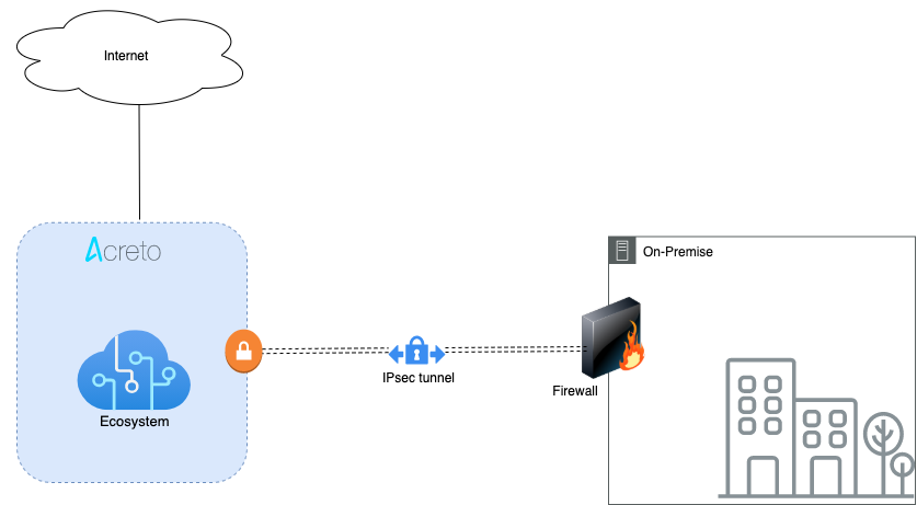
Prerequisites
- pfSense installation.
- Ecosystem set up with proper security policies.
Create Gateway for IPsec
Firstly, you will need to create a new Gateway device in the Acreto platform. Instructions on how to create a new Gateway are available here.
- Name: IPsec connection name must meet the exact requirements as the Strongswan connection name (letters and numbers only).
- Category: IoT
- Type: IPsec
- Allow connection from: Empty (describes the source IP address where the IPsec connection will be permitted).
- Local Networks: any local network addresses that will be routed through this gateway.
Info
To simplify testing, add the IP addresses of all interfaces connected to your gateway as Local Networks (you can use /32 prefix for public interface). This will allow you to test connectivity from the gateway through Acreto by using Ping, Traceroute, or similar tools.
How-To
Task 1: Read IPsec Gateway Values Required for IPsec Configuration
To proceed with the pfSense configuration, you will need a few values from an existing committed Acreto Gateway:
- Gateway Address
- Pre-Shared Key
- Recommended Ciphers
All of these may be found within the Gateway details panel - view the below animation for further instruction.
Animation how to get required values from Gateway [▶]
-
Log in to your pfSense panel.
-
Go to VPN > IPsec. Click on Add P1 to configure the Phase 1 settings.

-
In the following window, configure VPN Phase1 settings as below:
- General Information:
- IKE Exchange Version: IKEV2
- Internet Protocol: IPv4
- Interface: WAN
- Remote Gateway: Acreto Peer IP
- Description: AcretoVPN
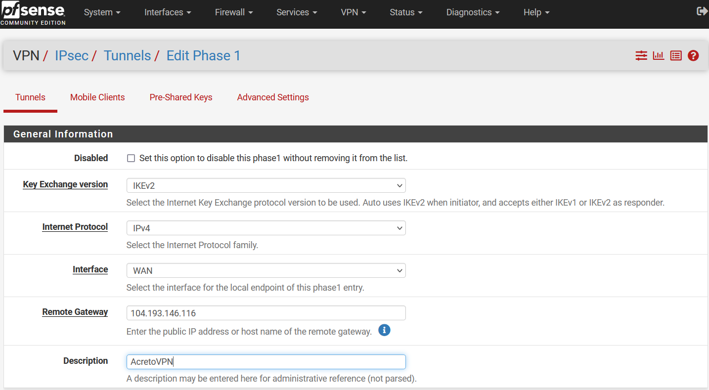
- Phase 1 Proposal (Authentication)
- Authentication Method: Mutual PSK
- My Identifier: select Distinguished Name and use Peer ID in the value field.
- Pre-Shared Key: PSK
- Phase 1 Proposal (Encryption Algorithm)
- Encryption Algorithm: AES 128 SHA256 15(3072)
- Expiration and Replacement
- Lifetime: 10800
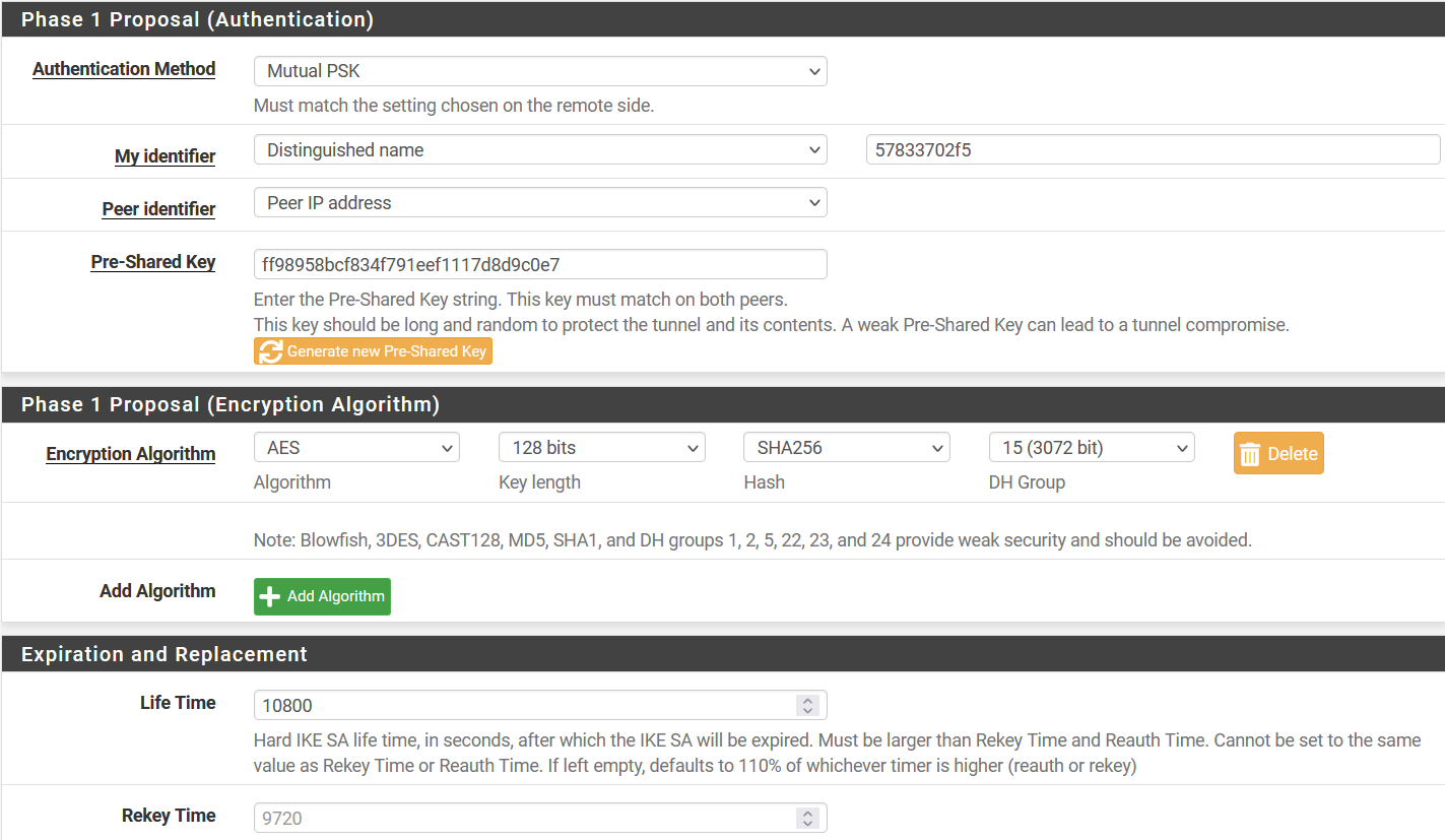
- Advanced Options
- Dead Peer Detection: Enable
- Delay: 30
- Max Failures: 5
-
Click Save to save the configuration.
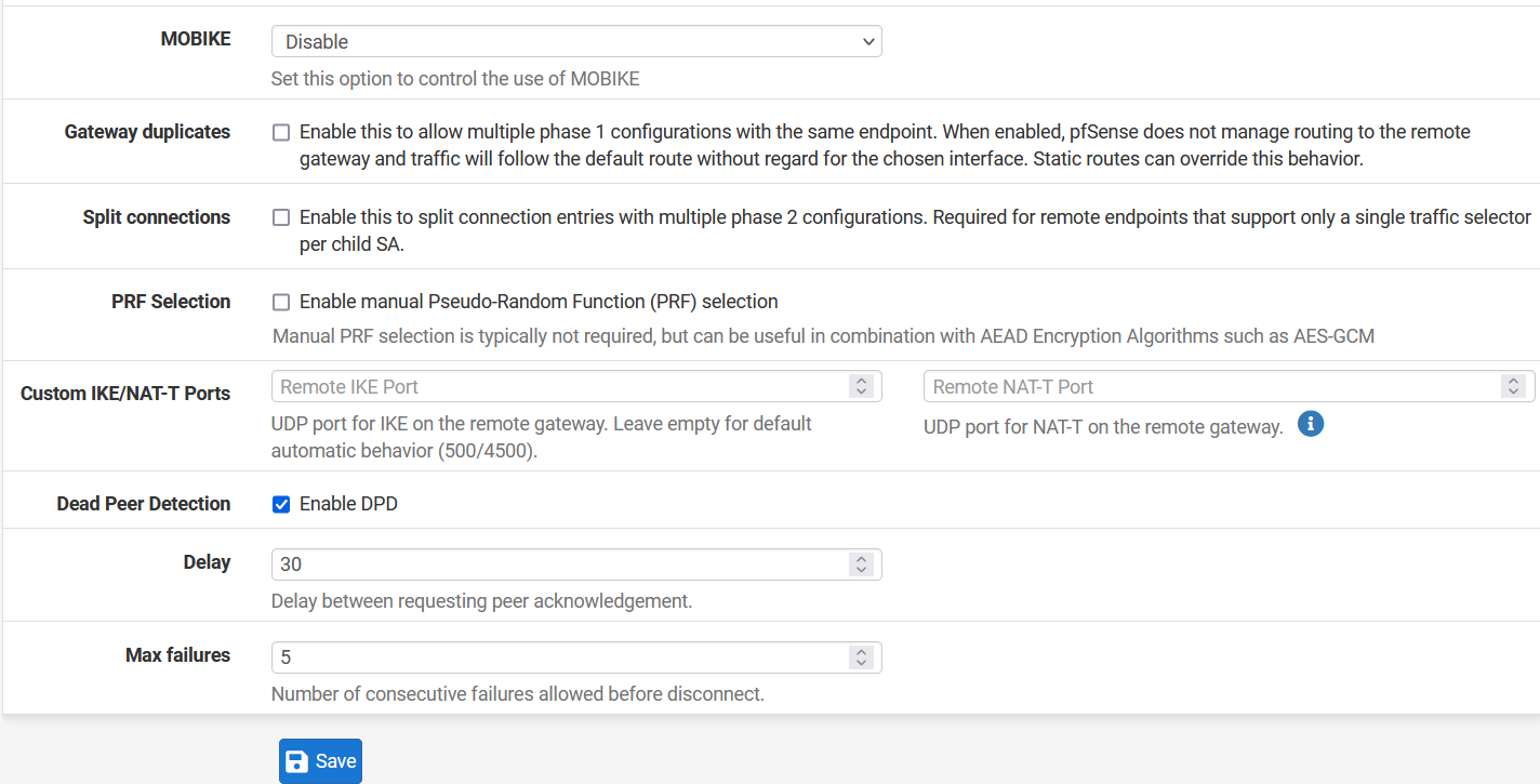
-
Click on Show Phase 2 Entries and Click on Add P2.
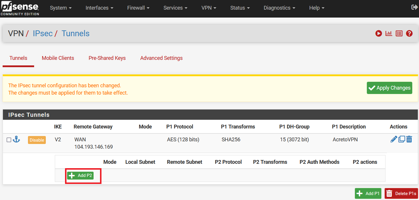
-
In the next window, configure the Phase 2 setting as below:
- General Information:
- Mode: Tunnel IPv4
- Local Network: Select Network and enter local network address 192.168.252.0/24
- Remote Network: Select Network and enter 0.0.0.0/0
- Description: AcretoVPN_P2
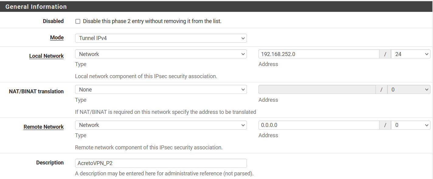
- Phase 2 Proposal (SA/Key Exchange)
- Protocol: ESP
- Encryption Algorithm: AES 128
- Hash Algorithm: SHA256
- PFS key group: 15 (3072)
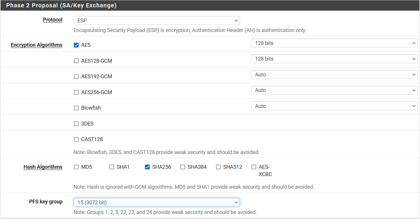
- Expiration and Replacement
- Lifetime: 3600 `
-
Click on Save.
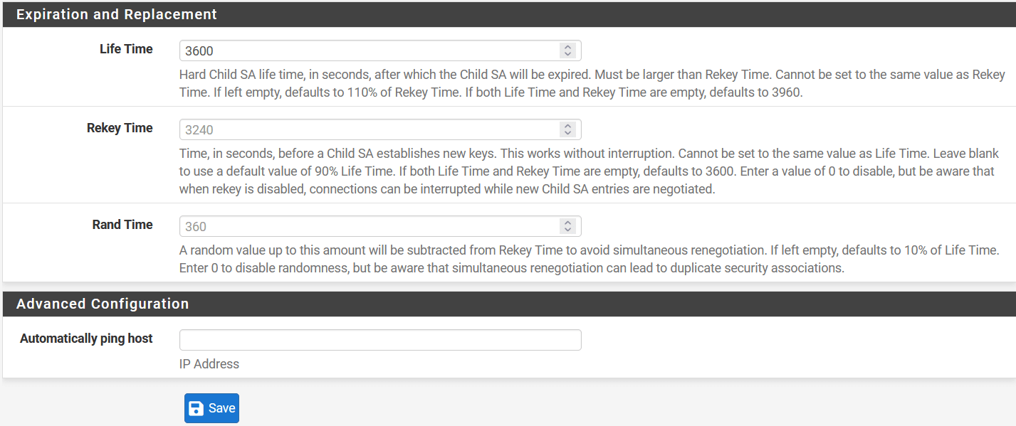
-
Click on Apply Changes to save the configuration.
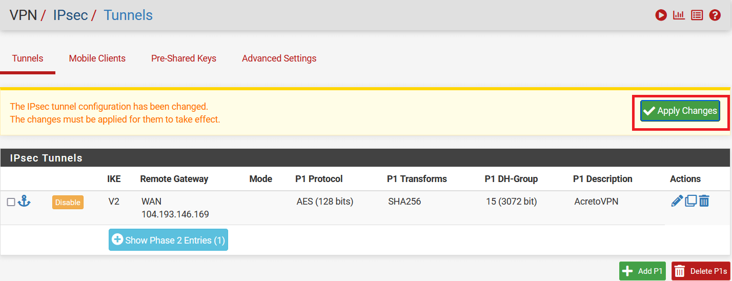
-
Go to Firewall > Rules and select LAN
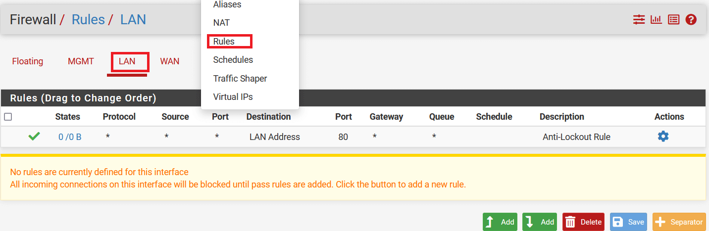
-
Click on Add button to add a new rule.
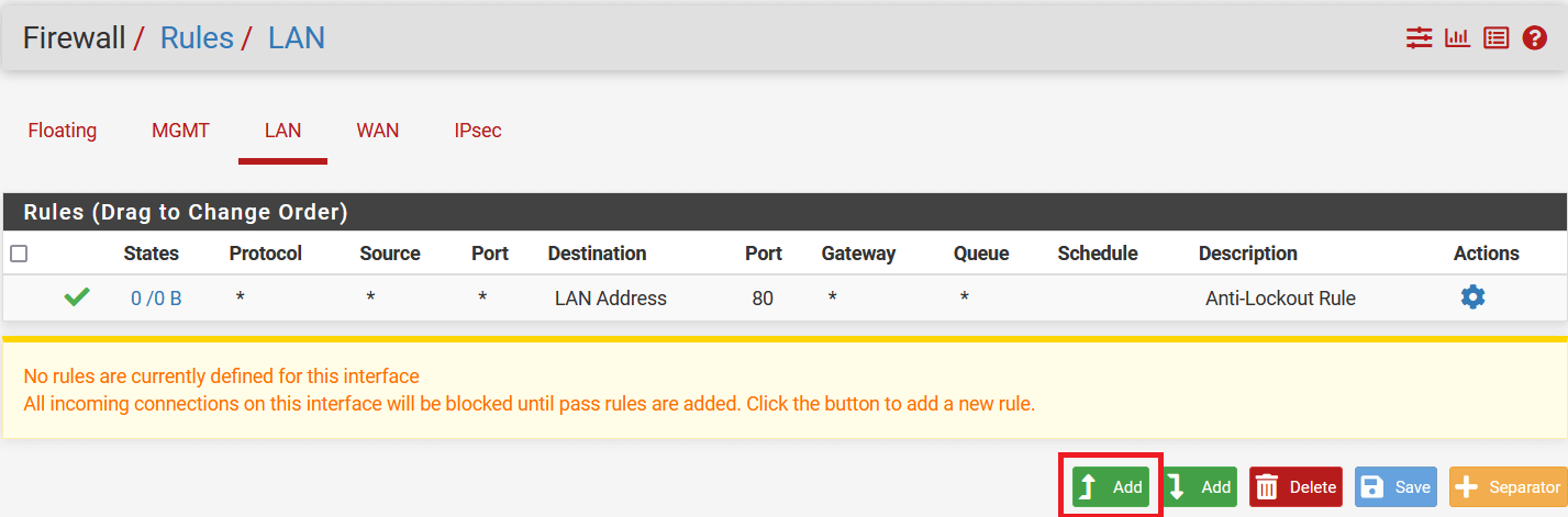
-
In the next window, configure policy as below:
- Edit Firewall Rules
- Action: Pass
- Interface: LAN
- Address Family: IPv4
- Protocol: Any
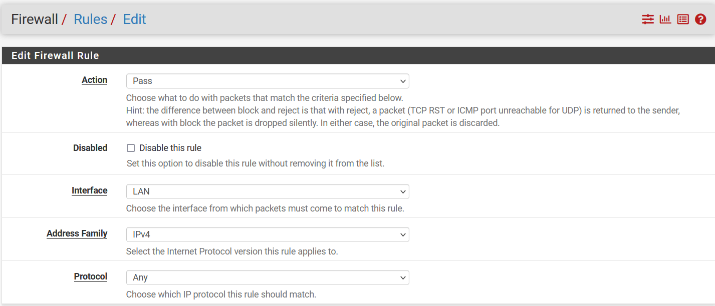
- Source
- Source: Select Network and enter local lan address i.e., 192.168.252.0/24
- Destination
- Destination: Any
- Click on Save
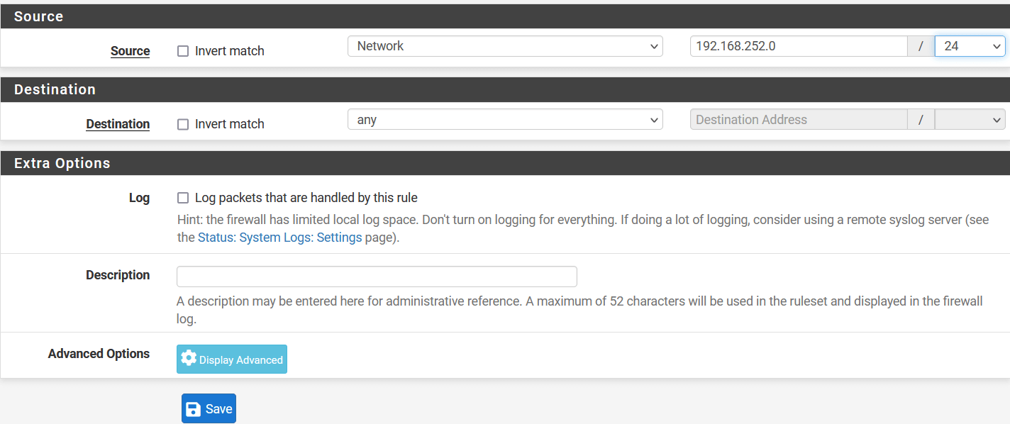
- Click on Apply Changes to save the configuration.
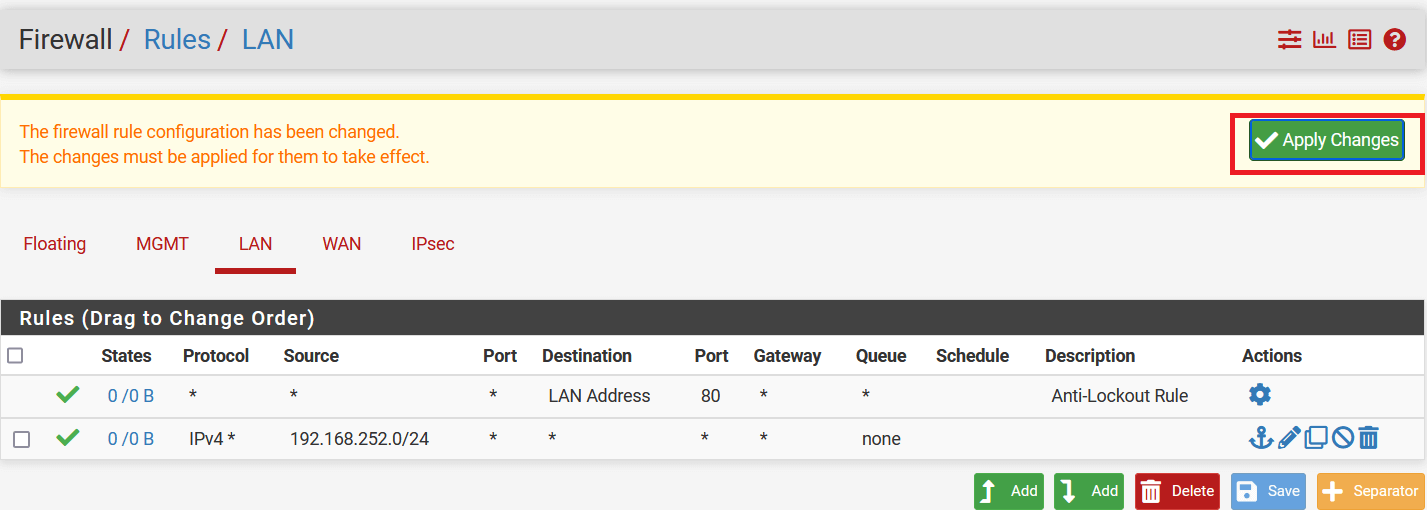
Task 4. Disable NAT for traffic over VPN
-
Go to Firewall > NAT.
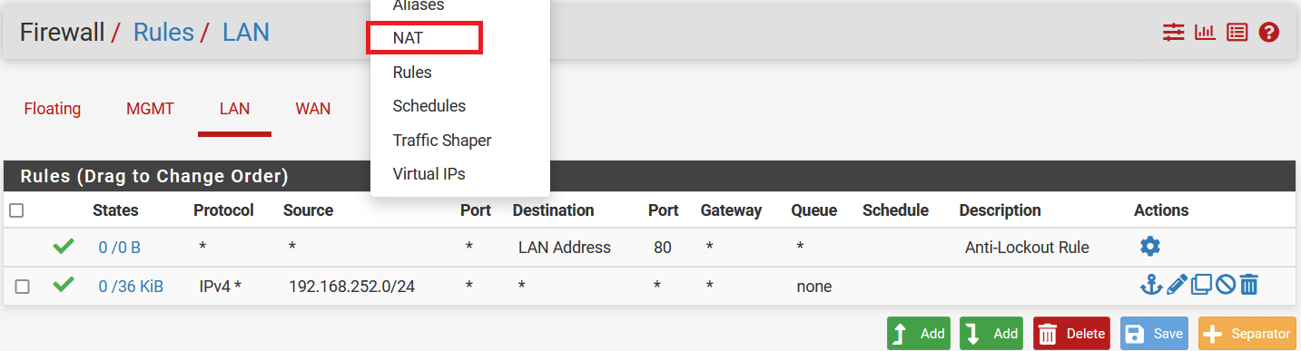
-
Select Outbound, and in the Mapping section click on the Add button.
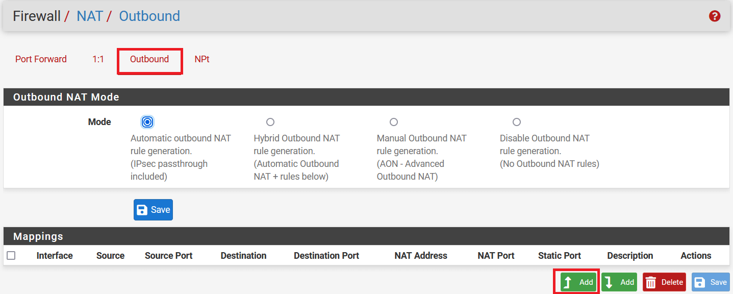
-
In the next window, configure the rule as below:
- Edit Advanced Outbound NAT Entry
- Do not NAT: Enable
- Interface: IPsec
- Address Family: IPv4
- Protocol: Any
- Source: Select Network and enter local lan address i.e., 192.168.252.0/24
- Destination: Any
-
Click on Save
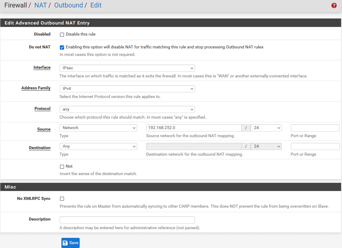
-
Click on Apply Changes to save the NAT rule.
-
In the same window, select mode Hybrid Outbound NAT rule generation. (Automatic Outbound NAT + rules below) in Outbound NAT Mode.
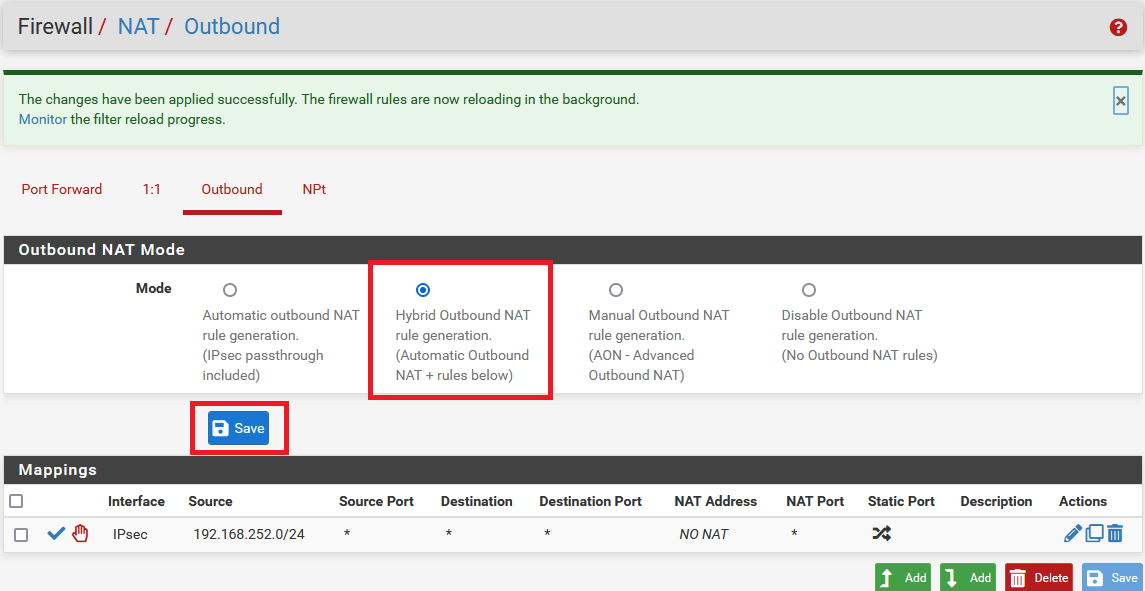
-
Click on Apply Changes to save settings.
Task 5. Verify Tunnel Status
-
Go to Status > IPsec.
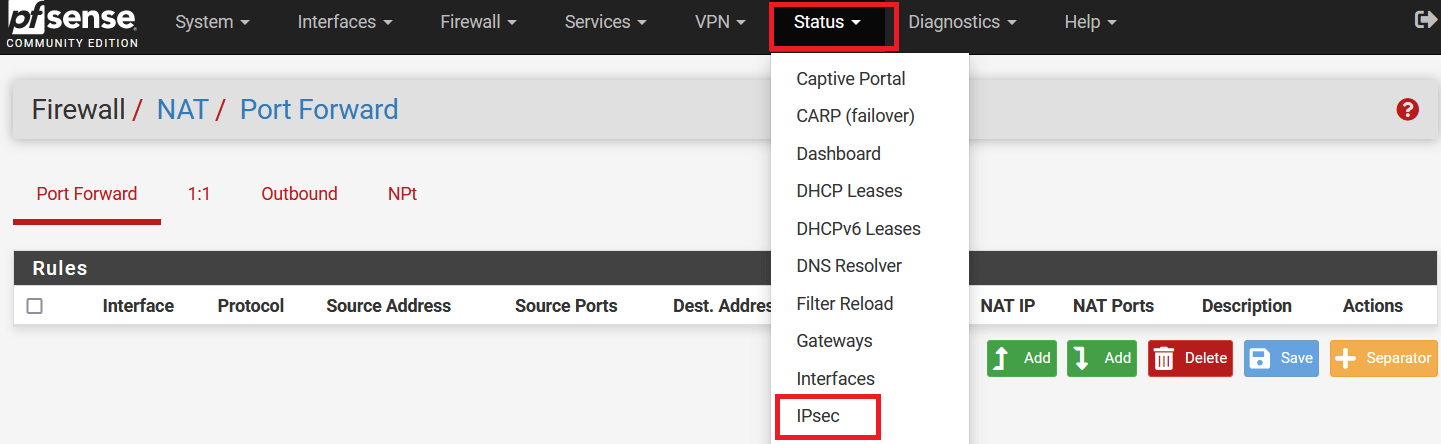
-
The following window will show the status of the VPN as below. Click on Connect VPN if the tunnel is down.
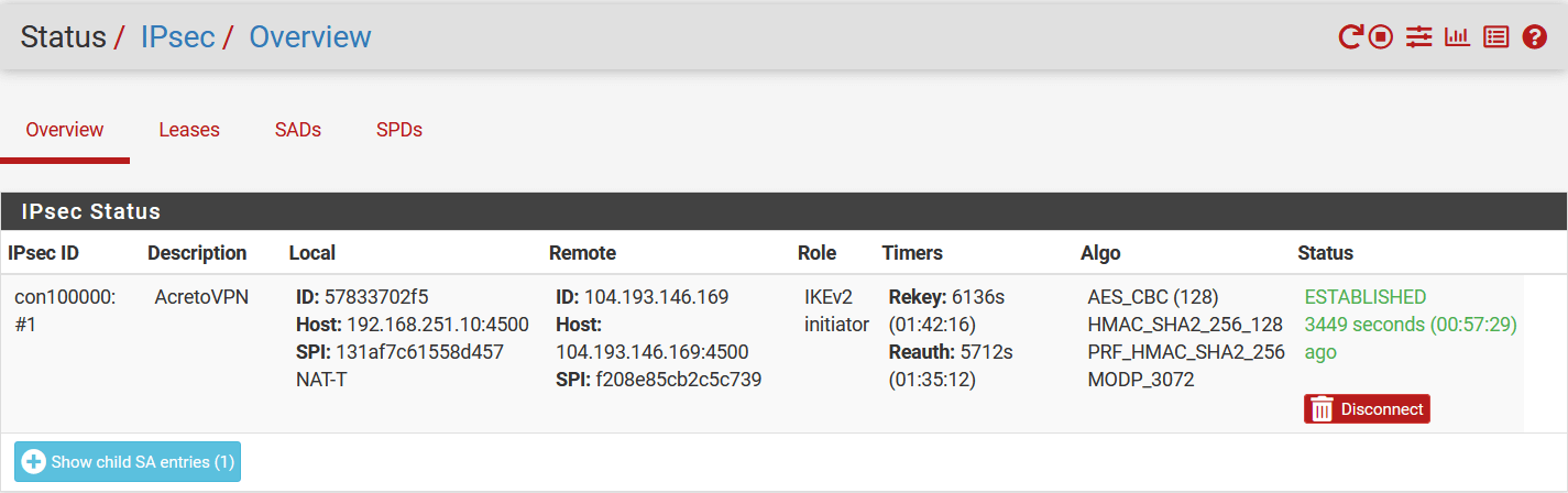
Task 6. Check the connectivity using the LAN interface
-
Go to Diagnostics » Ping.
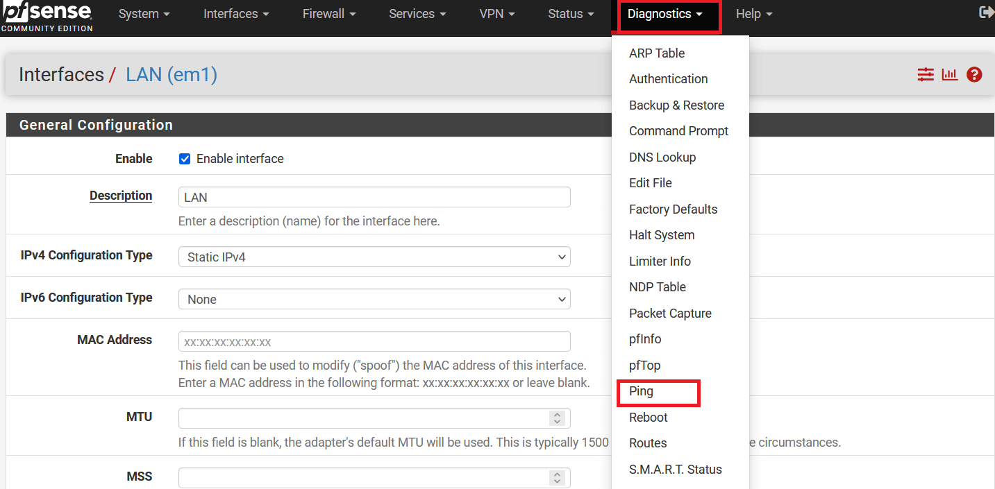
-
In the next windows, check ping as below:
- Hostname: 8.8.8.8
- Source address: LAN
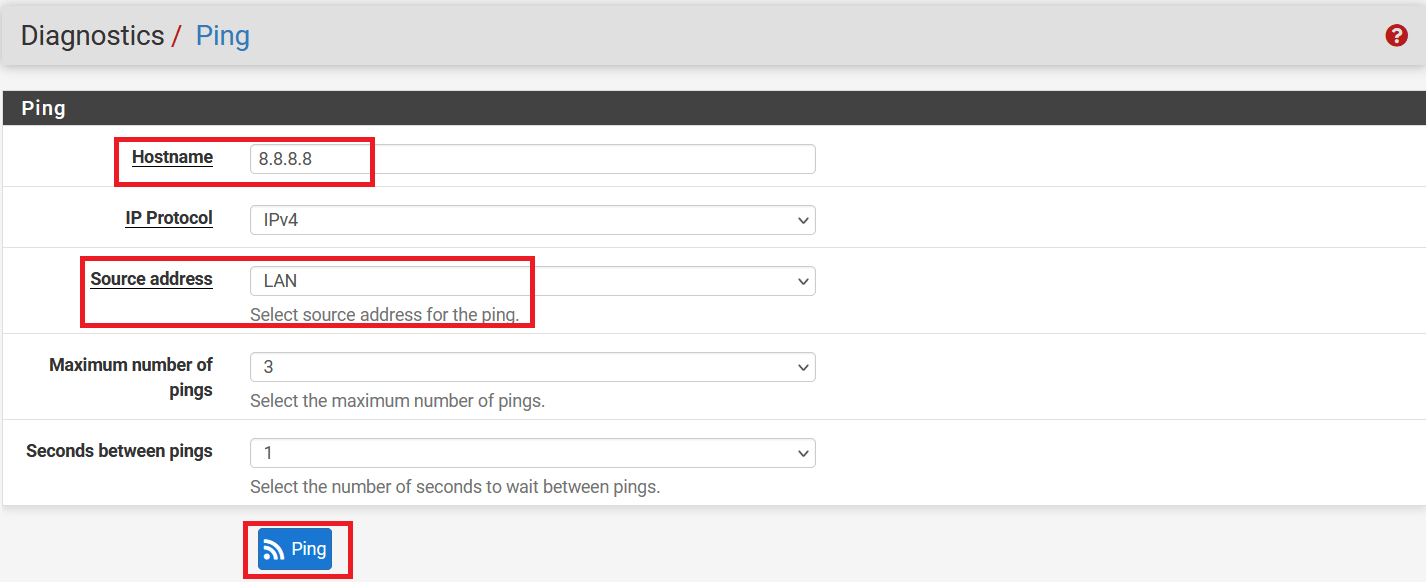
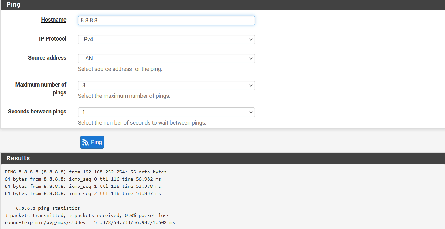
-
Ping should be successful, and logs on the Wedge dashboard should show the same record.
-
Go to VPN > IPsec and click on Advanced Setting.
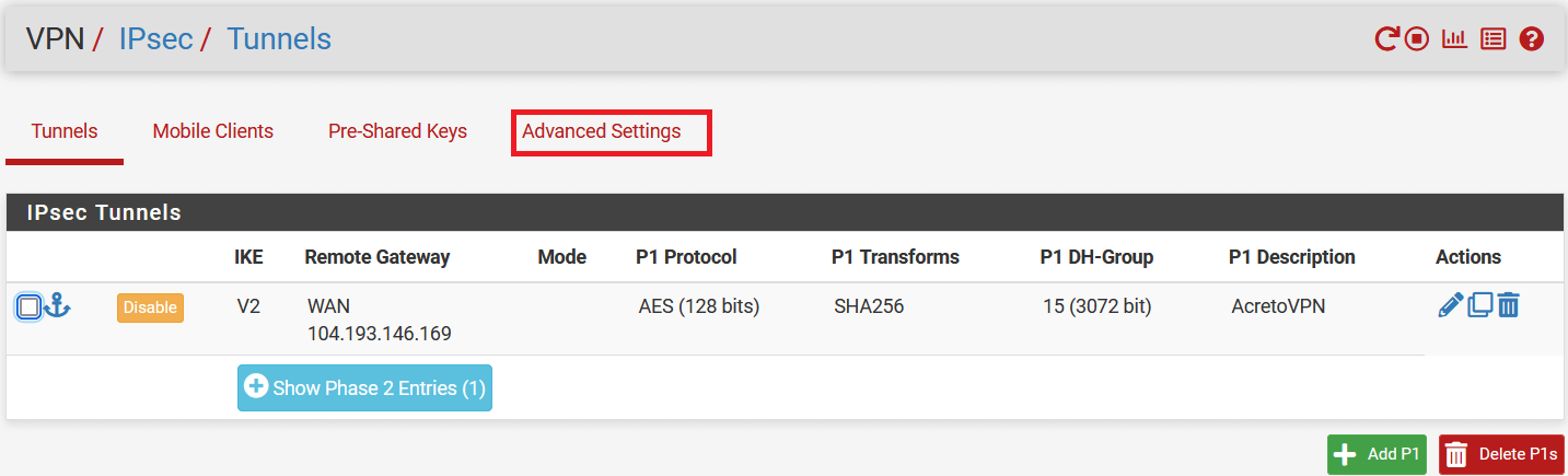
-
In IPsec bypass rules, enter the source and destinations of your local traffic, which doesn’t need to go through Acreto VPN.
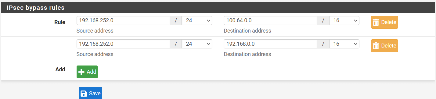
Summary
Once the VPN connection is successfully established, all the internet traffic will be routed through the Acreto.
Sonicwall 6.5 IPsec Configuration
Overview
In this article, you will learn how to connect your Sonicwall to the Acreto Ecosystem. To make it possible and secure, we will use the IPSec VPN connection.

Prerequisites
- Sonicwall 6.5 installation
- Ecosystem set up with proper security policies
Create Gateway for IPsec
Create a new Gateway device in the Acreto platform. Instructions on how to create a new Gateway are available here.
- Type: IPsec
- Category: Data Center
- Model: AWS site-to-site VPN
- Connections from: Public IP
- Local network: local_network
- Save and Commit the changes

Info
To simplify testing, add the IP addresses of all interfaces connected to your gateway as Local Networks (use /32 prefix for public interface). This allows testing connectivity from the gateway through Acreto by using Ping, Traceroute, or similar tools.
How-To
Task 1: Read IPsec Gateway Values Required for IPsec Configuration
To proceed with the Sonicwall configuration, you will need a few values from an existing committed Acreto Gateway:
- Gateway Address
- Pre-Shared Key
- Recommended Ciphers
All the details may be found within the Gateway details panel - please check the video below for further instructions.
Animation how to get required values from Gateway [▶]
To configure the IPsec VPN using tunnel interface, proceed with the following steps:
-
Goto MANAGE » VPN » Base Settings.
-
Under the VPN Policies click the ADD button
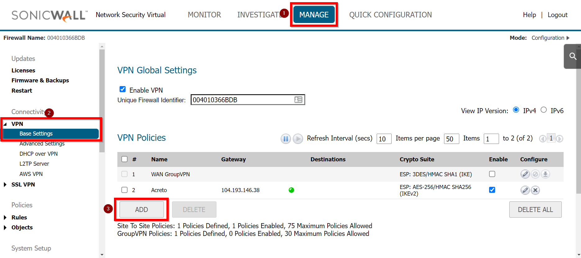
-
Under the General tab, enter the following values:
- Security Policy
- Policy Type: Tunnel Interface
- Authentication Method: IKE using Preshared Secret
- Name: Acreto
- IPsec Primary Gateway Name or Address: <Wedge_Tunnel_IP>
- IKE Authentication
- Shared Secret:
- Confirm Shared Secret:
- Local IKE ID: IPv4 Address: wedge_tunnel_IP
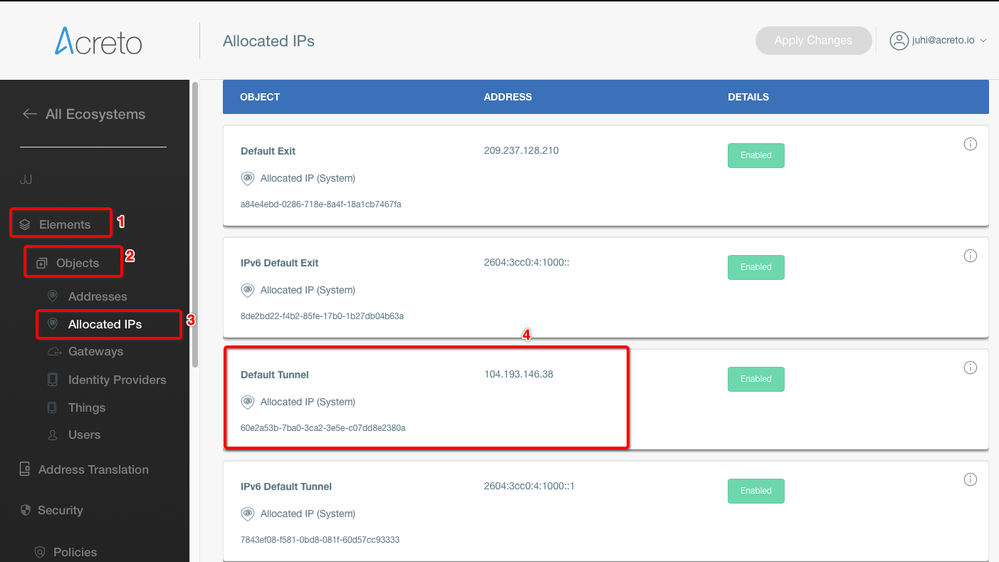
- Peer IKE ID: IPv4 Address: Local Public IP
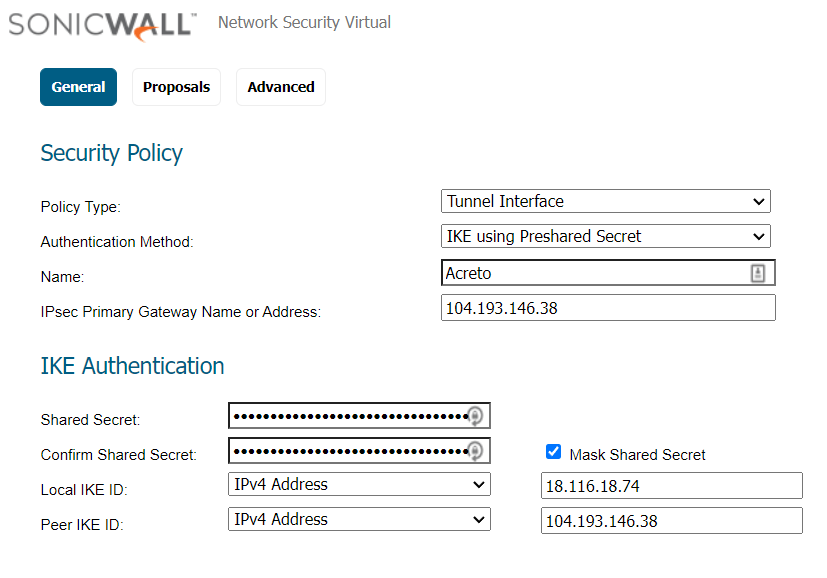
-
Goto Proposals
- IKE (Phase 1) Proposal
- Exchange: IKEv2 Mode
- DH Group: Group 2
- Encryption: AES-256
- Authentication: SHA256
- Life Time (seconds): 10800
- IPsec (Phase 2) Proposal
- Protocol: ESP
- Encryption: AES-256
- Authentication: SHA256
- Enable Perfect Forward Secrecy: Yes
- DH Group: Group 14
- Life Time (seconds): 3600
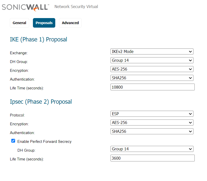
-
Advanced Settings
- Enable Keep Alive: Enable
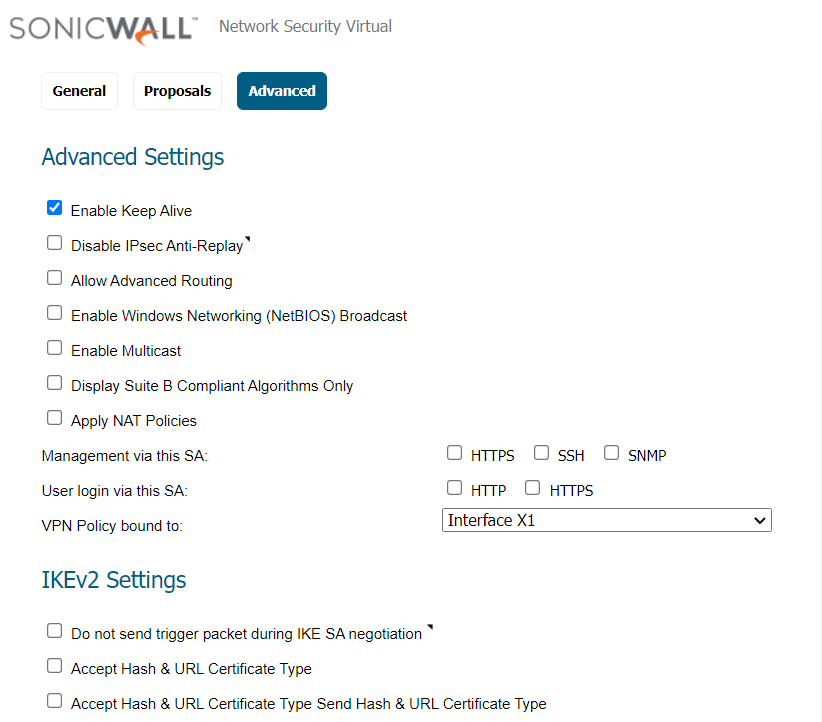
-
Click the OK button.
Task 3: Create a new tunnel interface
Next, we will create the tunnel interface that will be used to route the traffic.
-
Goto MANAGE » Network » Interfaces
-
In the middle of the screen, for the field Add Interface, select VPN Tunnel Interface.
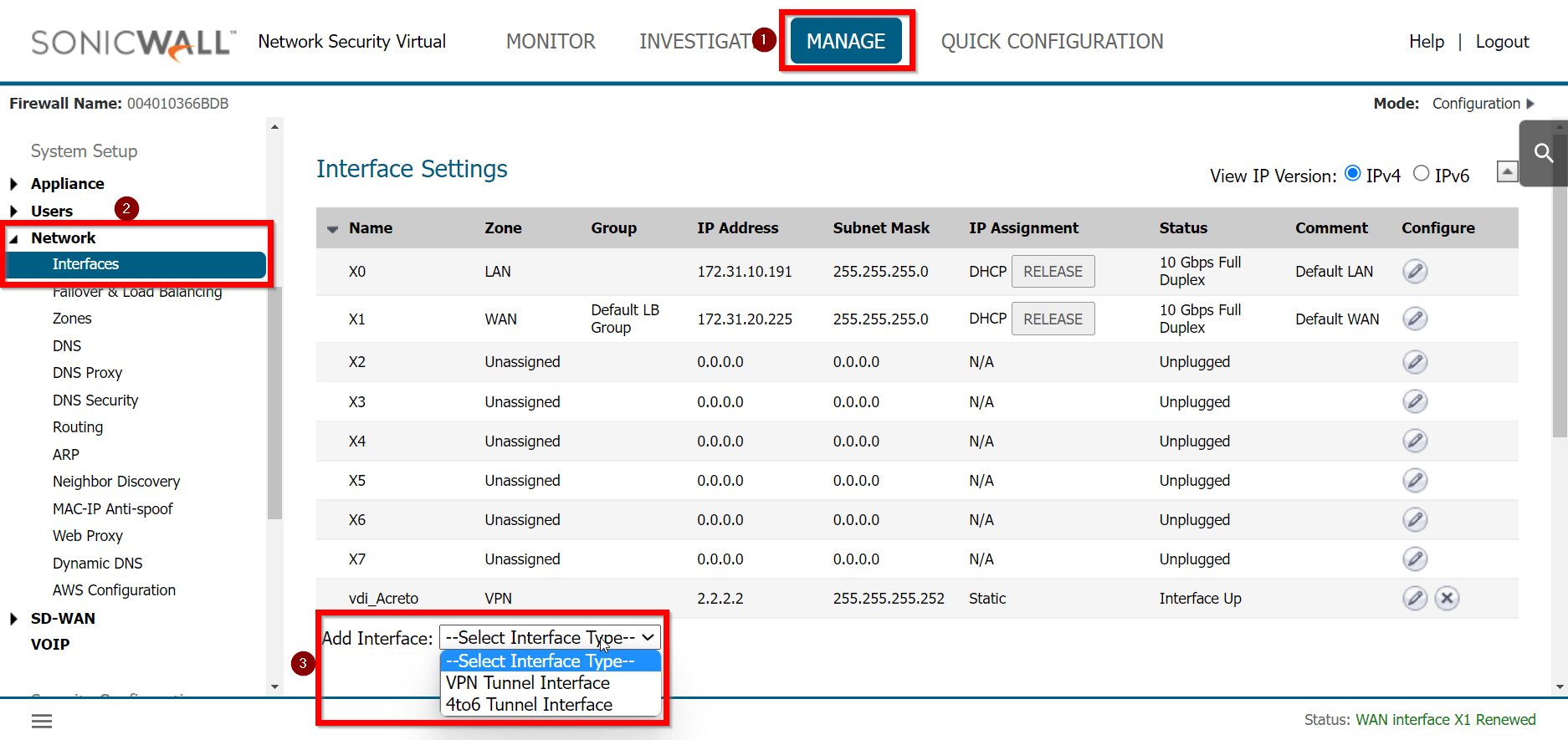
-
Create a new interface with the following values:
- VPN Policy: Acreto
- Name: vdi_Acreto
- IP Address: <any random IP as 2.2.2.2>
- Subnet Mask: 255.255.255.255
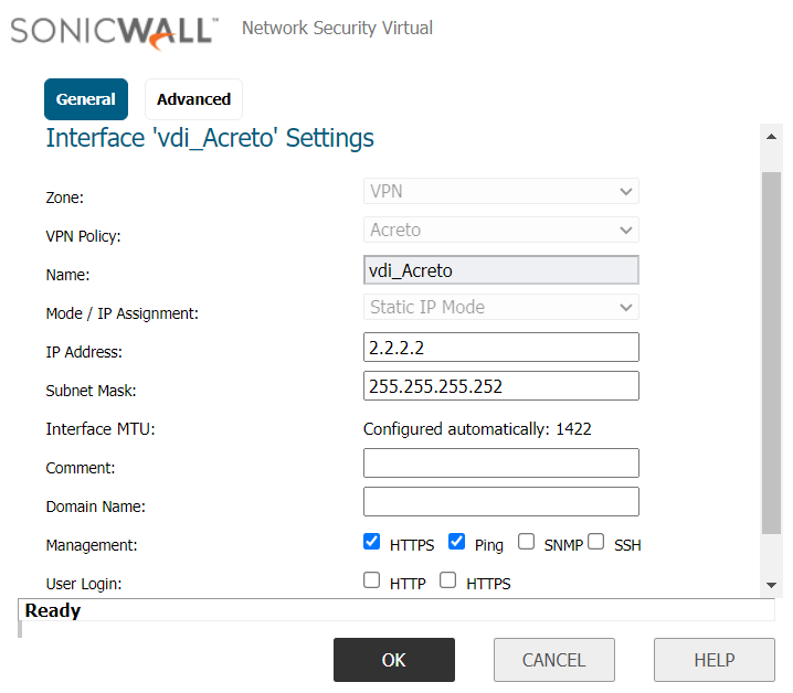
-
Click the OK button.
To allow the traffic from the LAN subnet to route through the tunnel interface, perform the following steps:
-
Goto MANAGE » Network » Routing
-
Under the tab Route Policies, click the Add button
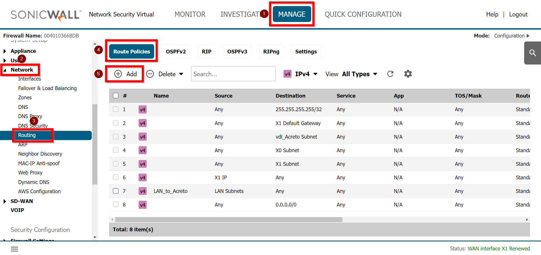
-
Create a new rule with the following values under General:
- Route Policy Settings
- Name: Lan_to_Acreto
- Source: <lan_subnets>
- Destination: Any
- Service: Any
- Interface: <tunnel_interface>
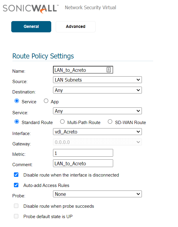
-
Click the OK button
Verify existing or create a new access rule to allow the desired traffic
-
Goto MANAGE » Rules » Access Rules
-
Click the Add button
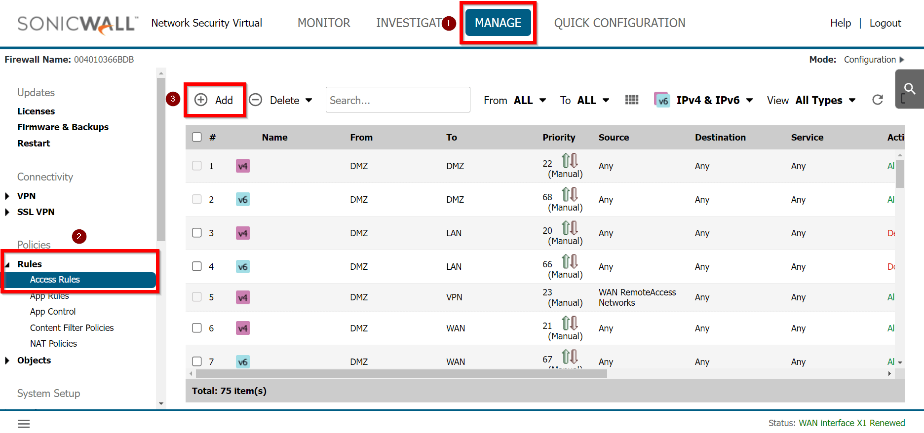
-
Under General, provide the following values:
- Name: To_Acreto
- Action: Allow
- From: <Lan_interface>
- To: <tunnel_interface>
- Source Port: Any
- Service: Any
- Source: <lan_subnet>
- Destination: Any
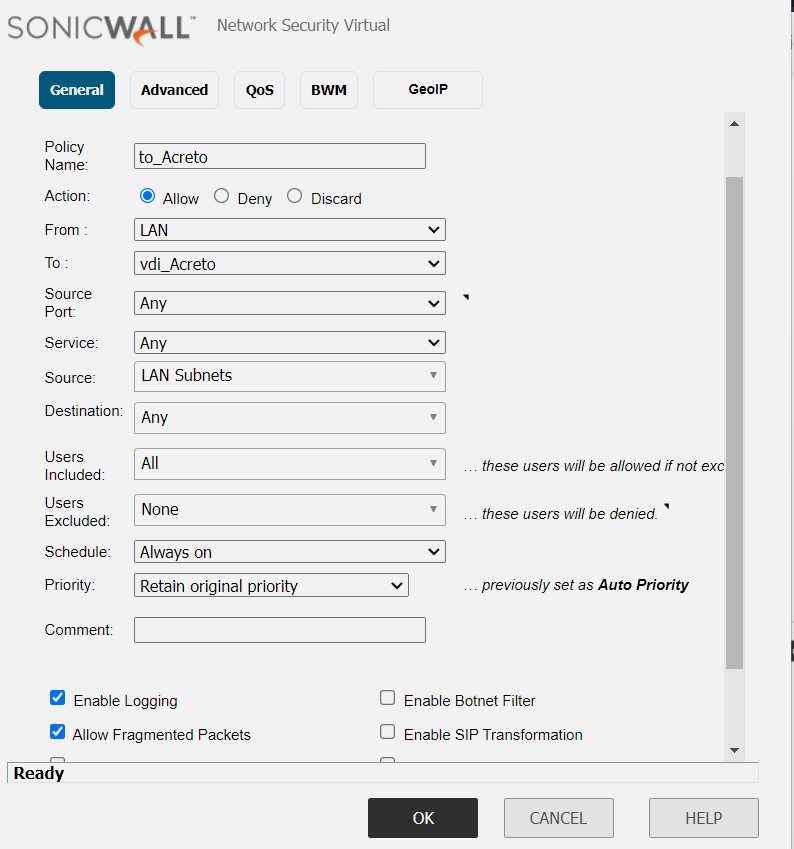
-
Click the OK button
Task 6: Verify the connection
Once the tunnel connection is successfully established, its status will change to UP.
-
To verify the status on Sonicwall, navigate to goto MANAGE » VPN » Base Settings
The status of the VPN policy should be Green.
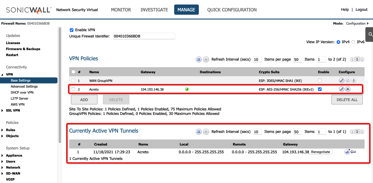
- Currently Active VPN Tunnels
The active VPN tunnel will be shown in the list.
-
Execute tracert 1.1.1.1 (or traceroute 1.1.1.1) on internal server check the route to external host 1.1.1.1. It should show Acreto’s IP in the path.

Summary
Once the VPN connection is successfully established, all the internal traffic to the internet will be routed through Acreto.
Sonicwall 7.0 IPsec Configuration
Overview
In this article, you will learn how to connect your Sonicwall to the Acreto Ecosystem. To make it possible and secure, we will use the IPSec VPN connection.

Prerequisites
- Sonicwall 7.0 installation
- Ecosystem set up with proper security policies
Create Gateway for IPsec
Create a new Gateway device in the Acreto platform. Instructions on how to create a new Gateway are available here.
- Type: IPsec
- Category: Data Center
- Model: AWS site-to-site VPN
- Connections from: Public IP
- Local network: local_network
- Save and Commit the changes
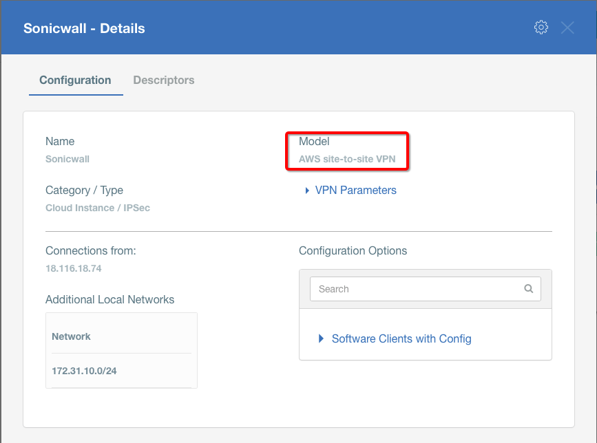
Info
To simplify testing, add the IP addresses of all interfaces connected to your gateway as Local Networks (use /32 prefix for public interface). This allows testing connectivity from the gateway through Acreto by using Ping, Traceroute, or similar tools.
How-To
Task 1: Read IPsec Gateway Values Required for IPsec Configuration
To proceed with the Sonicwall configuration, you will need a few values from an existing committed Acreto Gateway:
- Gateway Address
- Pre-Shared Key
- Recommended Ciphers
All the details may be found within the Gateway details panel - please check the video below for further instructions.
Animation how to get required values from Gateway [▶]
To configure the IPsec VPN using tunnel interface, proceed with the following steps:
-
Goto NETWORK » IPsec VPN » Rules and Settings.
-
Click the ADD button.
-
Under the General tab, enter the following values:
- Security Policy
- Policy Type: Tunnel Interface
- Authentication Method: IKE using Preshared Secret
- Name: Acreto
- IPsec Primary Gateway Name or Address: <Wedge_Tunnel_IP>
- IKE Authentication
- Shared Secret: PSK
- Confirm Shared Secret: PSK
- Local IKE ID: IPv4 Address: Wedge_tunnel_IP
- Peer IKE ID: IPv4 Address: Local Public IP
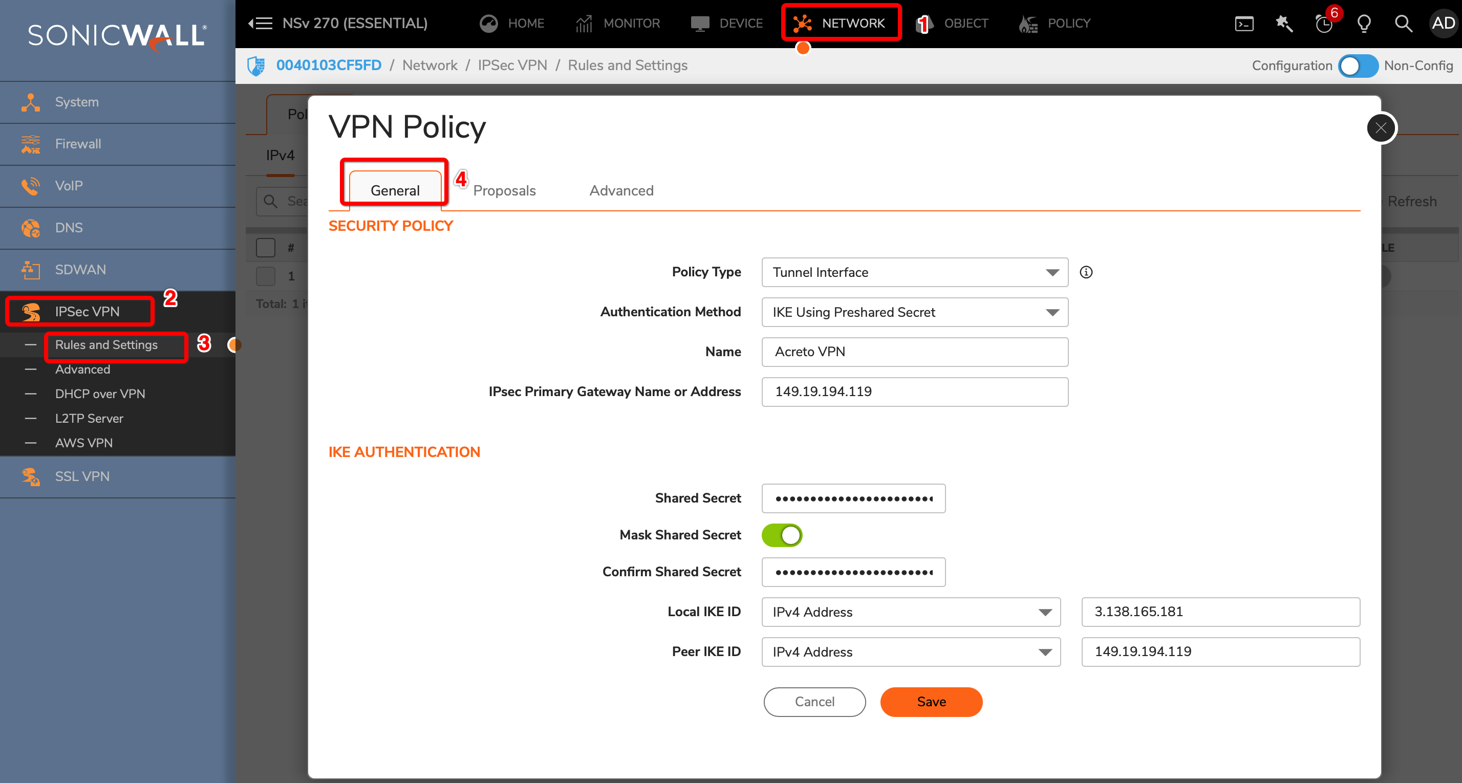
-
Goto Proposals
- IKE (Phase 1) Proposal
- Exchange: IKEv2 Mode
- DH Group: Group 2
- Encryption: AES-256
- Authentication: SHA256
- Life Time (seconds): 10800
- IPsec (Phase 2) Proposal
- Protocol: ESP
- Encryption: AES-256
- Authentication: SHA256
- Enable Perfect Forward Secrecy: Yes
- DH Group: Group 14
- Life Time (seconds): 3600
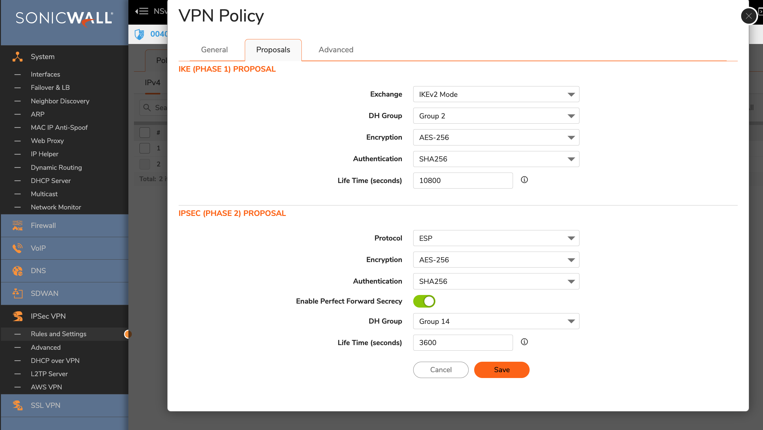
-
Advanced Settings
- Enable Keep Alive: Enable
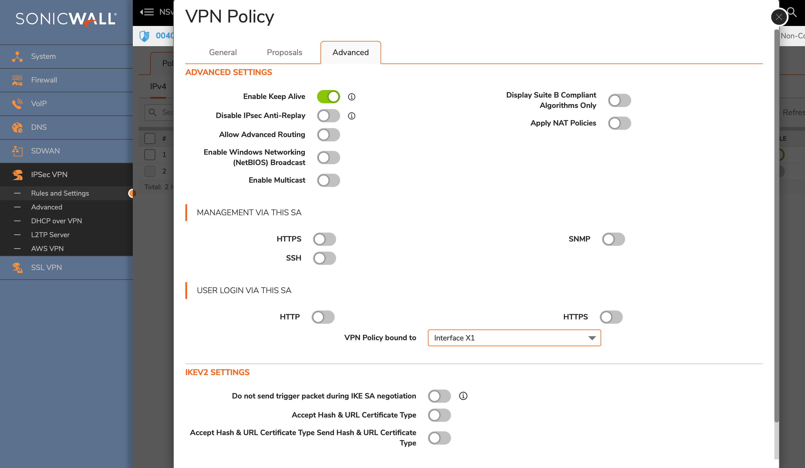
-
Click the OK button.
Task 3: Create a new tunnel interface
Next, we will create the tunnel interface that will be used to route the traffic.
-
Goto NETWORK » System » Interfaces.
-
Click the Add Interface button and select VPN Tunnel Interface
-
Create a new interface with the following values:
- VPN Policy: Acreto
- Name: vti_Acreto
- IP Address: <any random IP as 2.2.2.2>
- Subnet Mask: 255.255.255.254
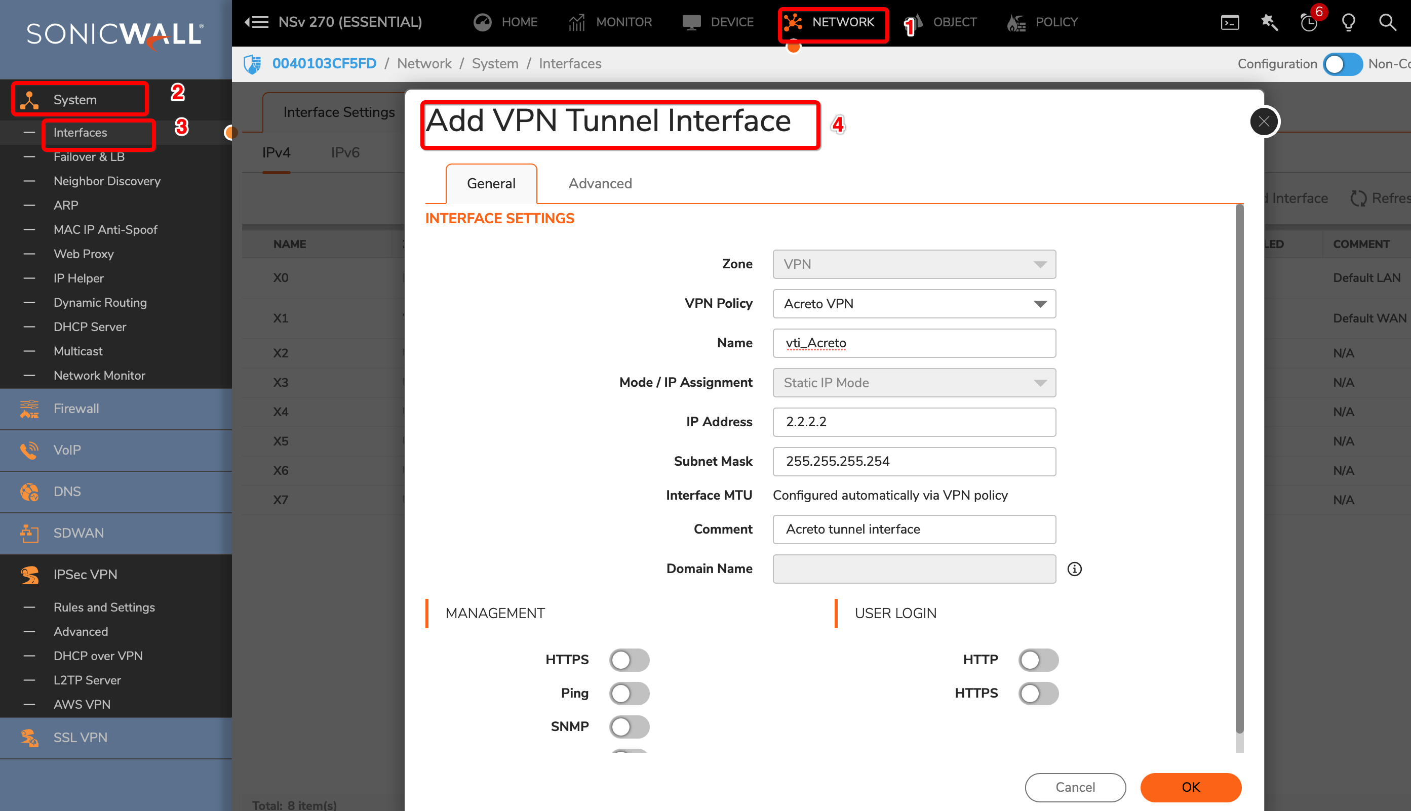
-
Click the OK button.
To allow the traffic from the LAN subnet to route through the tunnel interface, perform the following steps:
-
Goto POLICY » Rules and Policies » Route Policy
-
Create a new rule with the following values under General tab:
- Name: Lan_to_Acreto
- Source: <lan_subnets>
- Destination: Any
- Select Service radio button
- Service: Any
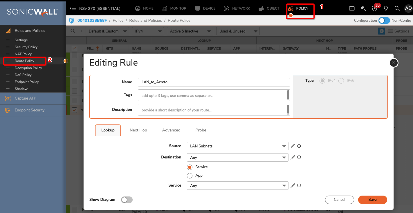
-
Click Next Hop tab and give the following values :
- Select Standard Route radio button
- Interface: <tunnel_interface>
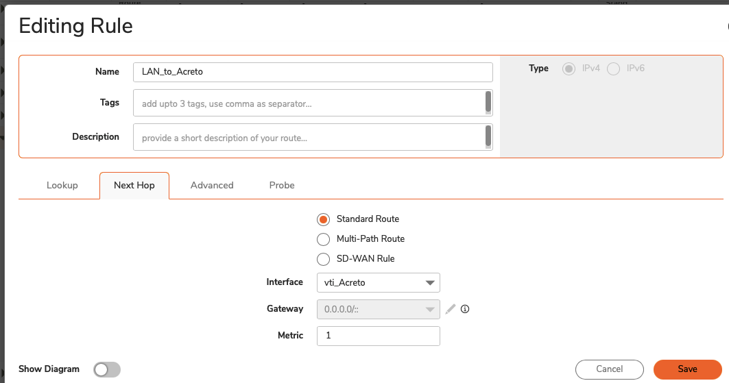
- Click the SAVE button
Verify existing or create a new access rule to allow the desired traffic
-
Goto POLICY » Rules and Policies » Security Policy
-
Click the Add button
-
Under General, provide the following values:
- Name: To_Acreto
- Action: Allow
- From: <Lan_interface>
- To: <tunnel_interface>
- Source Port: Any
- Service: Any
- Source: <lan_subnet>
- Destination: Any
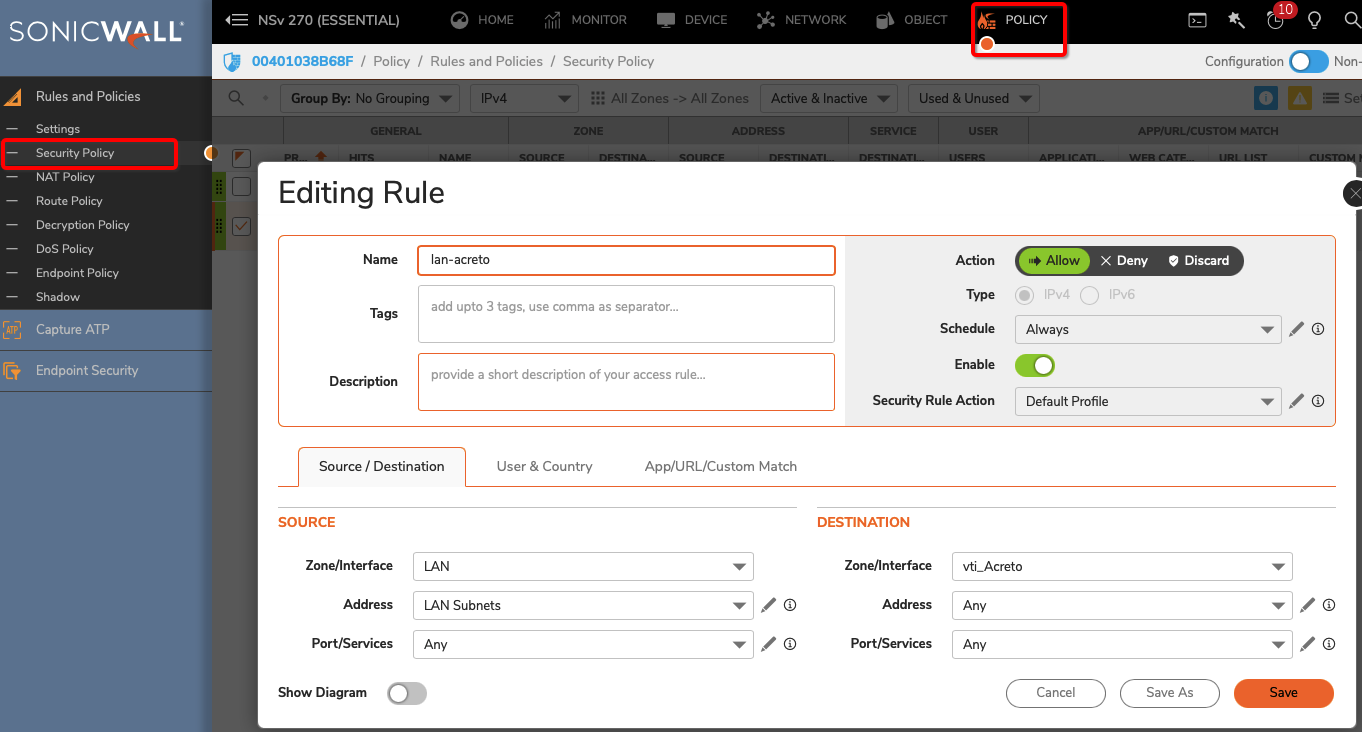
- Click the OK button
Task 6: Verify the connection
Once the tunnel connection is successfully established, its status will change to UP.
-
To verify the status on Sonicwall, navigate to goto NETWORK » IPsec VPN » Rules and Settings » Active Tunnels tab.
- The status of the VPN policy should be Green.
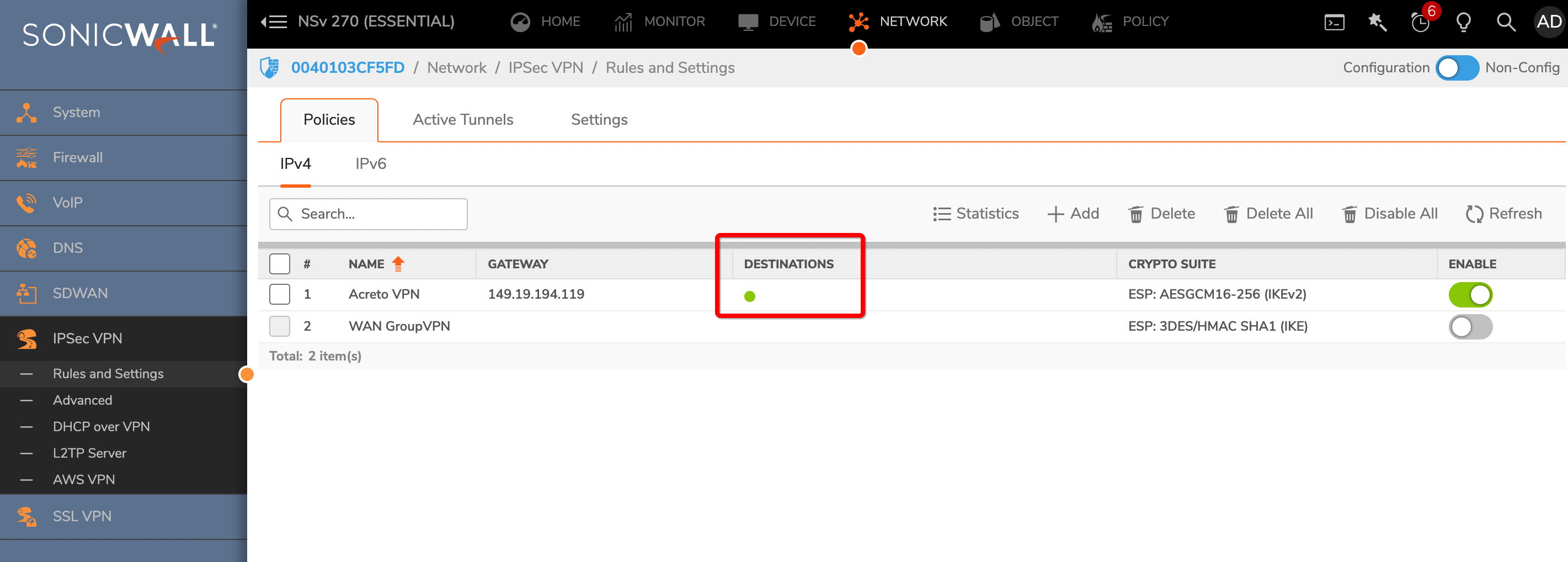
- Currently Active VPN Tunnels
The active VPN tunnel will be shown in the list.
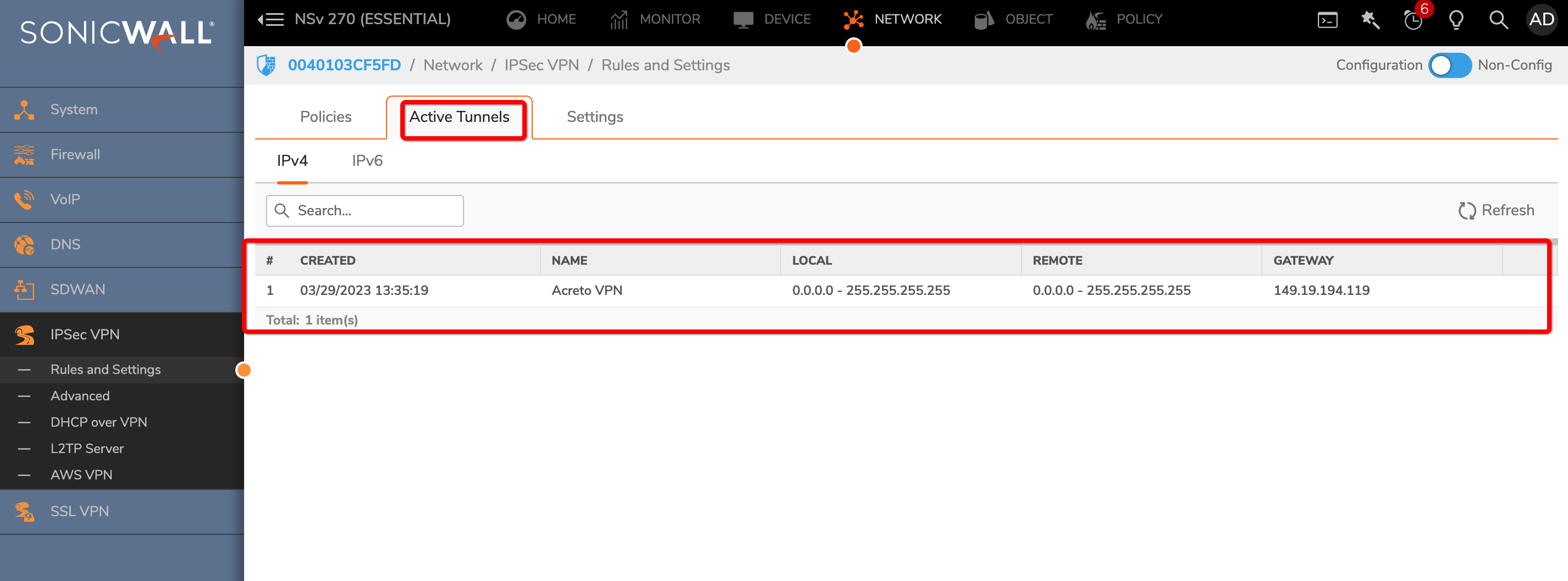
-
Execute tracert 1.1.1.1 (or traceroute 1.1.1.1) on internal server check the route to external host 1.1.1.1. It should show Acreto’s IP in the path.
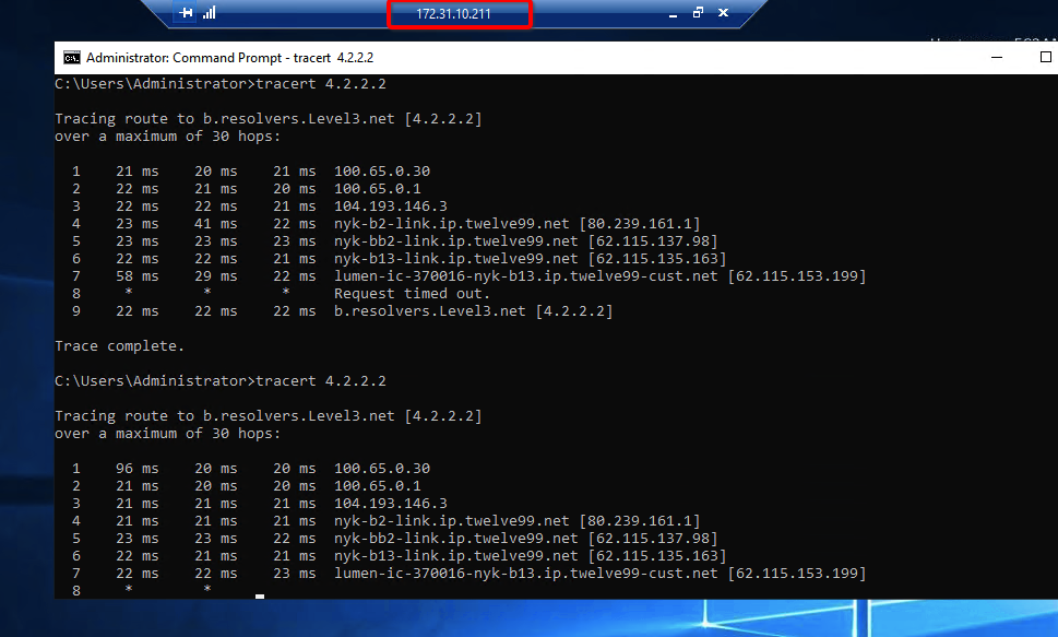
Summary
Once the VPN connection is successfully established, all the internal traffic to the internet will be routed through Acreto.
Sophos Ipsec with Acreto
Overview
This article will help you connect your Sophos XG with Acreto Ecosystem through the IPsec tunnel.
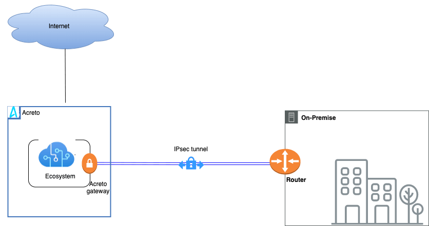
Prerequisites
- Sophos XG installation
- Ecosystem set up with proper security policies
Create Gateway for IPsec
Firstly, you will need to create a new Gateway device in the Acreto platform. Instructions on how to create a new Gateway are available here.
- Name: IPsec connection name must meet the same requirements as the Strongswan connection name (letters and numbers only).
- Category: IoT
- Type: IPsec
- Allow connection from: Empty (describes the source IP address where the IPsec connection will be permitted).
- Local Networks: any local network addresses that will be routed through this gateway.
Info
To simplify testing, add the IP addresses of all interfaces connected to your gateway as Local Networks (you can use /32 prefix for public interface). This will allow you to test connectivity from the gateway through Acreto by using Ping, Traceroute, or similar tools.
How-To
Task 1: Read IPsec Gateway Values Required for IPsec Configuration
To proceed with the Sophos configuration, you will need a few values from an existing committed Acreto Gateway:
- Gateway Address
- Pre-Shared Key
- Recommended Ciphers
All of these may be found within the Gateway details panel - view the below animation for further instruction.
Animation how to get required values from Gateway [▶]
-
Log in to the Sophos Firewall panel as a user with an administrator role.
-
From the left side navigation, choose Configure > VPN (1).
-
Move to the IPsec policies tab (2) and click on the Add button (3) to create a new policy.
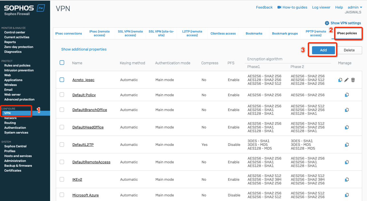
-
Fill the creation form with the following values:
-
General Settings
- Name: Acreto_ipsec
- Key exchange: ikev2
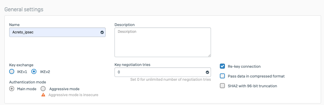
-
Phase1
- Key life: 10800
- DH group (key group): 14,16,20
- Encryption - Authentication:
- AES256 -SHA2 256
- AES128 - SHA2 256
- AES256 - SHA2 512
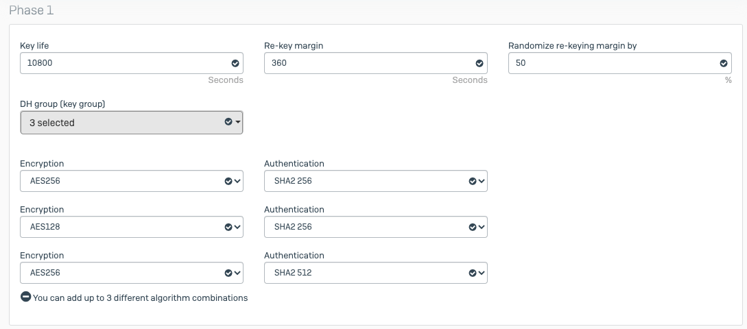
- Phase2
- PFS group (DH group): Same as phase1
- Key life: 3600
- Encryption - Authentication:
- AES256 -SHA2 256
- AES128 - SHA2 256
- AES256 - SHA2 512
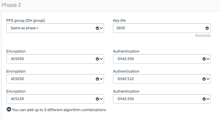
- Dead Peer Detection
- Dead Peer Detection: enable
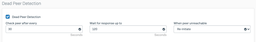
-
Click on the Save button to create the policy.
-
Goto VPN from left side navigator
-
Select tab IPsec connections and click Add button
-
Configure VPN with the following setting:
-
General Settings
- Name: Acreto
- IP version: IPv4
- Connection type: Tunnel interface
- Gateway type: Initiate the connection
- Activate on Save: enable
-
Encryption
- Policy: Acreto_ipsec
- Authentication type: Preshared key
- Preshared key: key (copied from Wedge)
- Repeat preshared key: key (copied from Wedge).
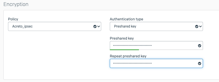
Gateway settings
-
Local gateway
- Listening interface: wan_ip
- Local ID type: DNS
- Local ID: peer_id (copied from Wedge)
-
Remote gateway
- Gateway address: acreto_gateway (copied from Wedge)
- Remote ID type: IP address
- Remote ID: acreto_gateway (copied from Wedge)
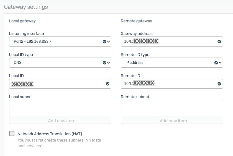
- Click Save.
Upon saving, the tunnel will try to establish a connection with Acreto, and upon successful connection, the tunnel will come up.
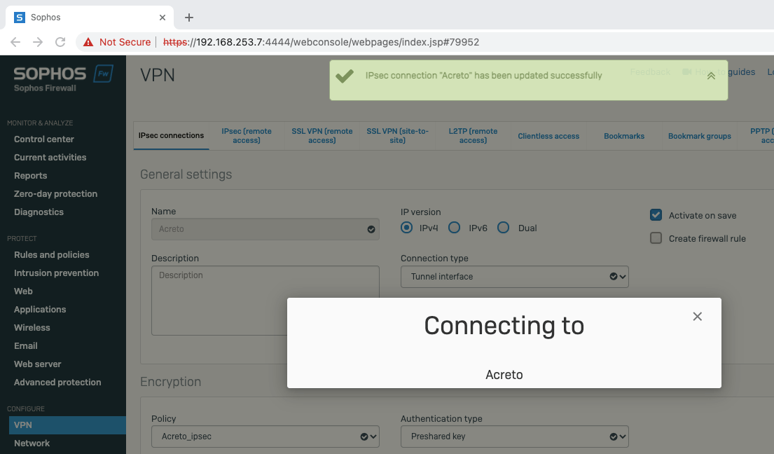
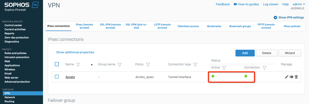
-
Goto Network from left side navigator
-
Select tab Network
-
Click the blue bar on the wan interface. It will unfold the new VPN tunnel interface formed
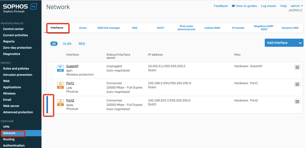
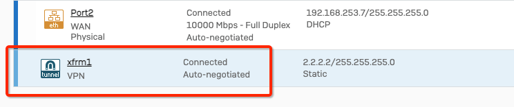
-
Click the tunnel interface and add some random IP
- IPv4/netmask - 2.2.2.2 /32
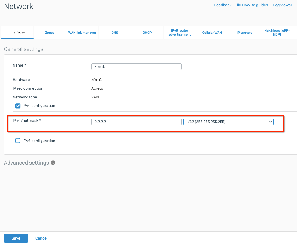
-
Click Save.
- Goto Routing from the left side navigator
- Select tab Static Routing
- Click Add button to configure the following routes
Direct route to Acreto gateway to establish the connection
- Destination IP/Netmask : acreto_gateway_ip /32 (copied from wedge)
- Gateway: ISP_gateway
- Interface: wan
- Distance: 0
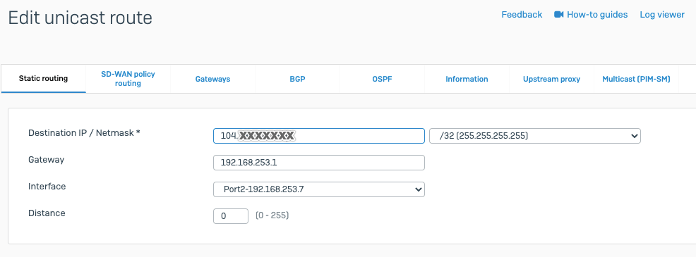
Default route to through the tunnel
- Destination IP/Netamsk: 0.0.0.0 /0
- Gateway: blank
- Interface: tunnel_inetrface
- Distance: 10
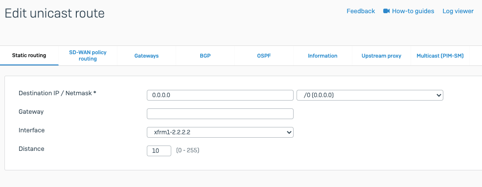
-
Goto Rules and policies from left side navigator
-
Select tab Firewall rules and click Add firewall rule to add a new firewall rule
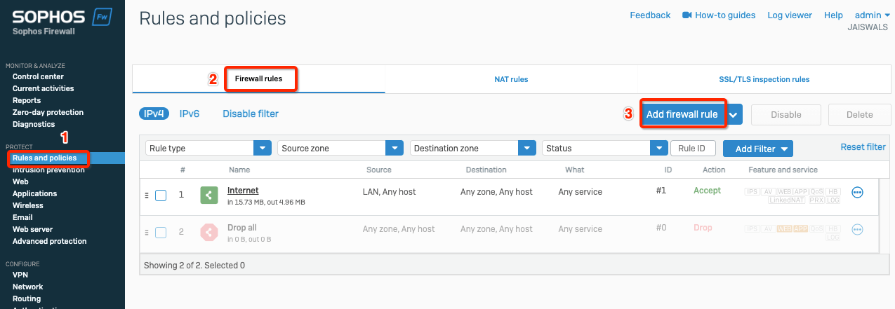
-
Create the firewall rule with values as below
Task 6: Verify the connection
Verify the connection is going through Acreto.
From any server in the internal subnet, do traceroute or mtr and verify if traffic is going through Acreto.
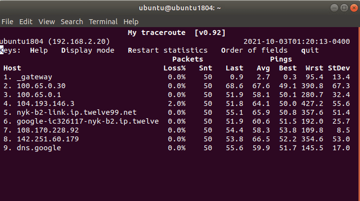
Summary
Once the VPN connection is successfully established, all the internal traffic to the internet will be routed through Acreto.
Troubleshooting - FortiGate Cloud Management issue
Issue
Forticloud management connection was lost after connecting to Acreto.
Description
When FortiGate is set up to route all traffic through Acreto, it may lose connection with FortiGuard/FortiCloud management servers.
Reason
When the default route is set towards Acreto, FortiGate sends all the FortiCloud connections through Acreto. However, while sending these requests, FortiGate uses its WAN IP as the source of the connection, which may not be allowed in Acreto EcoSystem.
To fix the issue, apply the solutions listed below:
Solution: Changes in FortiGate ( from the Customer side)
Alternatively, this issue can be resolved at the Customer location by setting Fortigate’s LAN IP as the source address for Fortiguard by following the steps below :
-
Login to Fortigate Dashboard
-
Goto Network > Interfaces > select the LAN interface
-
Copy the IP address of the LAN interface of FortiGate (Gateway IP for the LAN network)
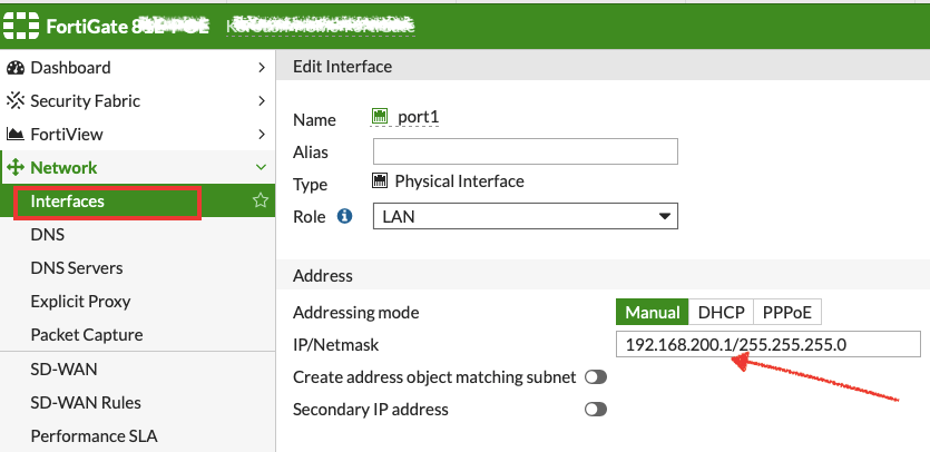
-
Login to CLI of FortiGate.
-
Run the following commands:
config system fortiguard
set source-ip <ip_address_lan_interface>
end
Any one of the above solutions will restore the connection with FortiCloud.
Ubiquiti Unifi IPsec Configuration
Overview
In this article, you will learn how to connect to the Acreto ecosystem with your Unifi USG/Edgerouter using IPSec VPN.
Prerequisites
- Ubiquiti USG/EdgeRouter installation
- Ecosystem set up with proper
security policies
How-To
Step1: Create Gateway for IPsec
Firstly, you will need to create a new Gateway device in the Acreto platform. Instructions on how to create a new Gateway are available here.
If you already have one, make sure that it’s IPsec type and jump to How-to.
- Name: IPsec connection name must meet the same requirements as the Strongswan connection name (letters and numbers only).
- Category: IoT
- Type: IPsec
- Allow connection from: Empty (describes the source IP address where the IPsec connection will be permitted).
- Local Networks: any local network addresses that will be routed through this gateway.
Info
To simplify testing, add the IP addresses of all interfaces connected to your gateway as Local Networks (you can use /32
prefix for public interface). This will allow you to test connectivity from the gateway through Acreto by using Ping, Traceroute, or similar
tools.
Step 2: Read the IPsec Gateway Values Required for Ubiquiti Configuration from Acreto Ecosystem
To proceed with the Ubiquiti configuration, you will need a few values from an existing committed Acreto Gateway:
- Gateway Address
- Pre-Shared Key
- Recommended Ciphers
- Peer ID

All of these may be found within the Gateway details panel - view the below animation for further instruction.
Animation how to get required values from Gateway [▶]
-
Login into Ubiquiti and enter Configuration mode
-
Enable the auto-firewall-nat-exclude feature which automatically creates the IPsec firewall/NAT policies in the iptables firewall.
set vpn ipsec auto-firewall-nat-exclude enable.
-
Create the IKE / Phase 1 (P1) Security Associations (SAs) by providing the following values
set vpn ipsec ike-group AcretoGate key-exchange ikev2
set vpn ipsec ike-group AcretoGate lifetime 10800
set vpn ipsec ike-group AcretoGate proposal 1 dh-group 16
set vpn ipsec ike-group AcretoGate proposal 1 encryption aes256
set vpn ipsec ike-group AcretoGate proposal 1 hash sha256
-
Create the ESP / Phase 2 (P2) SAs.
set vpn ipsec esp-group AcretoGate lifetime 3600
set vpn ipsec esp-group AcretoGate proposal 1 encryption aes256
set vpn ipsec esp-group AcretoGate proposal 1 hash sha256
set vpn ipsec esp-group AcretoGate compression disable
-
Execute the below command using values from previous steps:
Configure the below steps with values for Gateway address, Preshared key and Peer Id collected in Step 1.
- GATEWAY_ADDRESS - available in step 1, number 1 on screen.
- PRE-SHARED KEY - available in step 1, number 2 on screen.
- PEER ID - available in step 1, number 4 on screen.
set vpn ipsec site-to-site peer GATEWAY_IP_ADDRESS authentication mode pre-shared-secret
set vpn ipsec site-to-site peer GATEWAY_IP_ADDRESS authentication pre-shared-secret PRE-SHARED_KEY
set vpn ipsec site-to-site peer GATEWAY_IP_ADDRESS description ipsec
set vpn ipsec site-to-site peer GATEWAY_IP_ADDRESS authentication id PEER_ID
-
Copy the WAN IP and router address from the Ubiquiti gateway device

-
Use the above WAN IP and conFigure the Peer with the below commands
set vpn ipsec site-to-site peer GATEWAY_IP_ADDRESS local-address LOCAL_WAN_INTERFACE
-
Link the SAs created in the above steps to the remote peer and bind the VPN to a virtual tunnel interface (vti0).
set vpn ipsec site-to-site peer GATEWAY_IP_ADDRESS ike-group  AcretoGate
set vpn ipsec site-to-site peer GATEWAY_IP_ADDRESS vti bind vti0
set vpn ipsec site-to-site peer GATEWAY_IP_ADDRESS vti esp-group AcretoGate
-
Configure a static route to route gateway address to the internet directly. Use router address copied from step 6.
set protocols static route GATEWAY_IP_ADDRESS next-hop ROUTER_IP_ADDRESS
-
Configure default static route to send all traffic to Acreto VPN.
set protocols static interface-route 0.0.0.0/0 next-hop-interface vti0
-
Commit the changes and save the configuration.
Summary
Once the VPN connection is successfully established, all the internet traffic will be routed through Acreto.
Watchguard IPsec Configuration
Overview
This article will show you how to configure the Watchguard to connect to the Acreto Ecosystem. This configuration will be made by using IPsec VPN.
Prerequisites
- Watchguard installation
- Ecosystem set up with proper
security policies
How-To
Step 1: Create Gateway for IPsec
Firstly, you will need to create a new Gateway device in the Acreto
platform. Instructions on how to create a new Gateway are available
here.
- Name: IPsec connection name must meet the same requirements as
the Strongswan connection name (letters and numbers only).
- Category: IoT
- Type: IPsec
- Allow connection from: Empty (describes the source IP address
where the IPsec connection will be permitted).
- Local Networks: any local network addresses that will be routed
through this gateway.
Info
To simplify testing, add the IP addresses of all
interfaces connected to your gateway as Local Networks (you can use /32
prefix for public interface). This will allow you to test connectivity
from the gateway, or similar
tools.
Step 2: Read the Values from Acreto Gateway
To proceed with the Watchguard configuration, you will need a few values
from an existing committed Acreto Gateway:
- Gateway Address
- Pre-Shared Key
- Peer ID
- Recommended Ciphers
All of these may be found within the Gateway details panel - view the
below animation for further instruction.
Animation how to get required values from Gateway [▶]
-
Create Phase 2 proposal - Navigate to VPN > Phase 2 Proposals and click ADD button

-
Create Phase 2 with the following values and SAVE
- Name: Acreto
- Description: Acreto phase2 selectors
- Type: ESP
- Authentication: SHA-512
- Encryption: AES(128-bit)
- Time: 1 hour

-
To set up IPsec VPN navigate to VPN > BOVPN Virtual Interfaces and click ADD from the right pane

-
Select Remote Endpoint Type as Cloud VPN or Third-Party Gateway

-
Provide the Preshared key copied from the Wedge dashboard in Step 1 and click ADD button to configure Gateway Endpoint

-
Configure Local gateway - Select Interface By Domain Name and provide the Peer ID copied from Wedge dashboard in Step 1.

-
Configure Remote gateway with values copied in Step 1 and click OK
- Static IP Address : Wedge_gateway
- By IP Address: Wedge_gateway

-
Click Phase 1 Settings tab

-
the following values
- Version: IKEv2
- Keep-alive interval: 540 seconds
- Traffic-idle timeout: 30 seconds

- Select the Phase 1 Transform set in Transform Settings and click EDIT. Set the following values and click OK.
- Authentication: SHA2-512
- Encryption: AES(28-bit)
- SA Life: 3 hours
- Key Group: Diffie-Hellman Group 15

- Click Phase 2 Settings and configure Phase 2 with values as below
- Enable Perfect Forward Secrecy: Diffie-Hellman Group 15
Select Acreto from Phase 2 proposal and ADD and SAVE.

- Verify the tunnel status - Navigate to SYSTEM STATUS > VPN Statistics > Branch Office VPN and click IKEv2 Virtual Interface. If the VPN is successfully established, the statistics related to VPN will be displayed.

Summary
Once the VPN connection is successfully established, all the internet traffic will be routed through Acreto.
Subsections of Acreto vGateway
Install vGateway on Windows Server - example of implementation
Overview
In this article, you’ll learn how to run Acreto vGateway on a Windows Server machine. This process involves the following steps:
- Configuration of Acreto Ecosystem
- Image installation
- Connectivity check
Before You Start
Case study
In this example, our target is to connect the existing virtual server to Acreto Ecosystem. The selected server works as a Virtual Machine based on Windows Server 2019 Hyper-V. In the same data center/cloud exist also other servers connected to different internal LANs but using the same Internet Router. The existing configuration was presented in the below diagram.
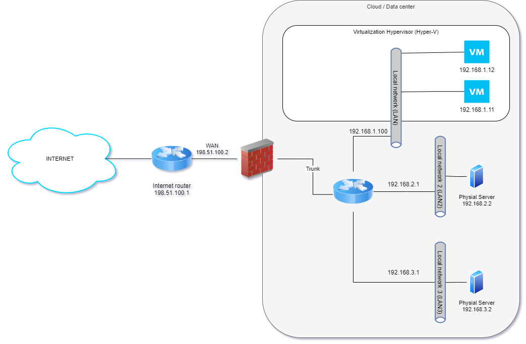
To connect the selected server to Acreto Ecosystem we will use the vGateway - a small virtual machine-generated by Acreto Wedge. This machine will be installed on the same host that other virtual machines in Data Center and connected to the same internal network. Also, network routing will be changed to redirect “external traffic” from/to the selected server thru Acreto vGateway.
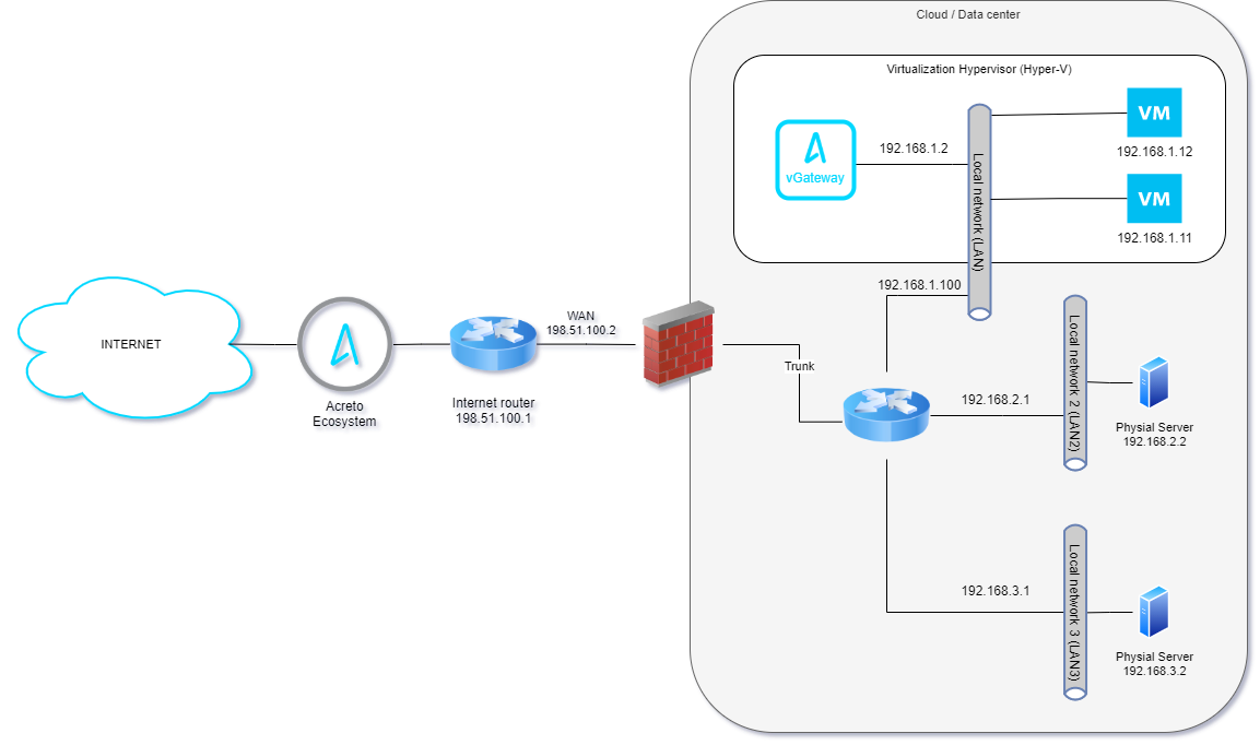
The step-by-step procedure will be described in the below article.
Prerequisities
To run vGatway on Hyper-V, you will need:
- Active Acreto Ecosystem.
- Windows Server machine.
- Get familiar with Introduction to vGateway.
- Knowledge of network infrastructure and routing rules.
Configuration of Acreto Ecosystem
- Log in to an Acreto platform at wedge.acreto.net
- Select your ecosystem and go to Objects (1) using the left menu.
- Click Add new Object(2) and select the Gateway Option.
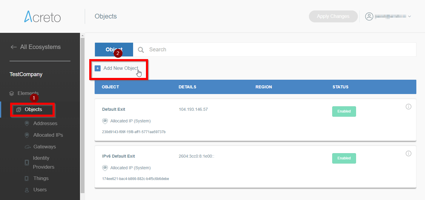
- Fill at least:
- Name: - the name of the created gateway. Needs to be compatible with Strongswan connection name requirements (basically, only letters and numbers). In this example- s01gateway
- Category: IoT
- Switch Gateway type to vGateway and set the specific setting for vGateway:
- DHCP/Static: - select the method of assigning addresses on the network> In this example - Static
- vGateway Internet IP - IP address with a netmask of internet-facing (WAN) interface. In this example: 198.51.100.2/24
- vGateway Default Route - IP address of your Internet gateway/router that allows access to the Internet, for example 1.2.3.1. In this example 198.51.100.1
- vGateway Local IP: - address of local (LAN) interface of your device. In this example 192.168.1.2/32
- Local Networks: - your local network addresses that should be routed through this gateway.
In this example fill only the left field in the row: 192.168.1.12/32.
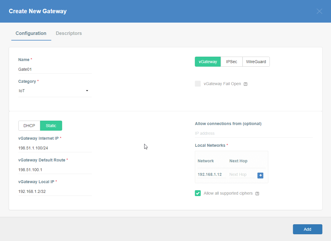
- Save the created Gateway by pressing Add.
- Add security policy that will allow communication from the Gateway device to the Internet:
- From the left menu choose the Policies option (1), then click on the + Add New Policy button (2).
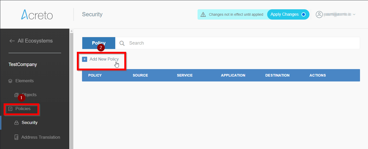
- Fill the form with values similar to that from the screen.
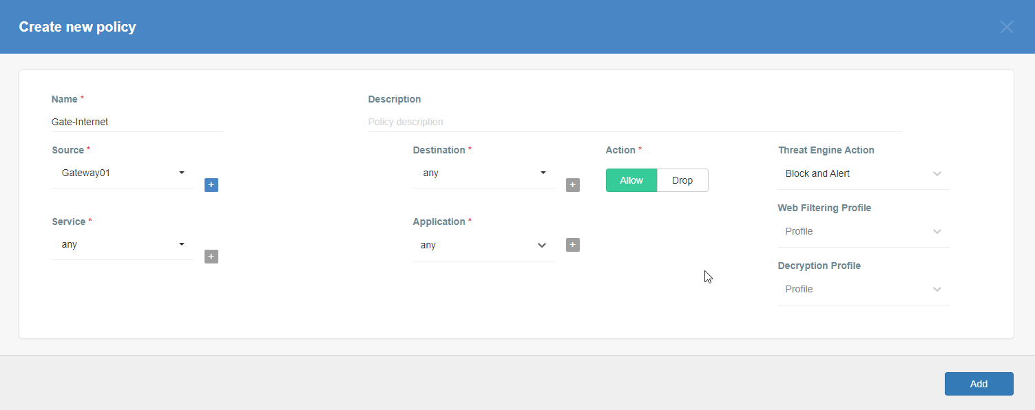
- Save the new policy by clicking on the Add button.
- Commit pending changes (top of the screen)
- Go to Elements > Objects > Gateways menu position.
- On the list of existing gateways choose this created in the previous step, click on its name.
- Choose VM and Cloud Images to expand the available option for download virtual images.
- Click on Play for Microsoft Hyper-V .vhdx vGateway Image option. Generation of image for you Gateway may take a while, please be patient.
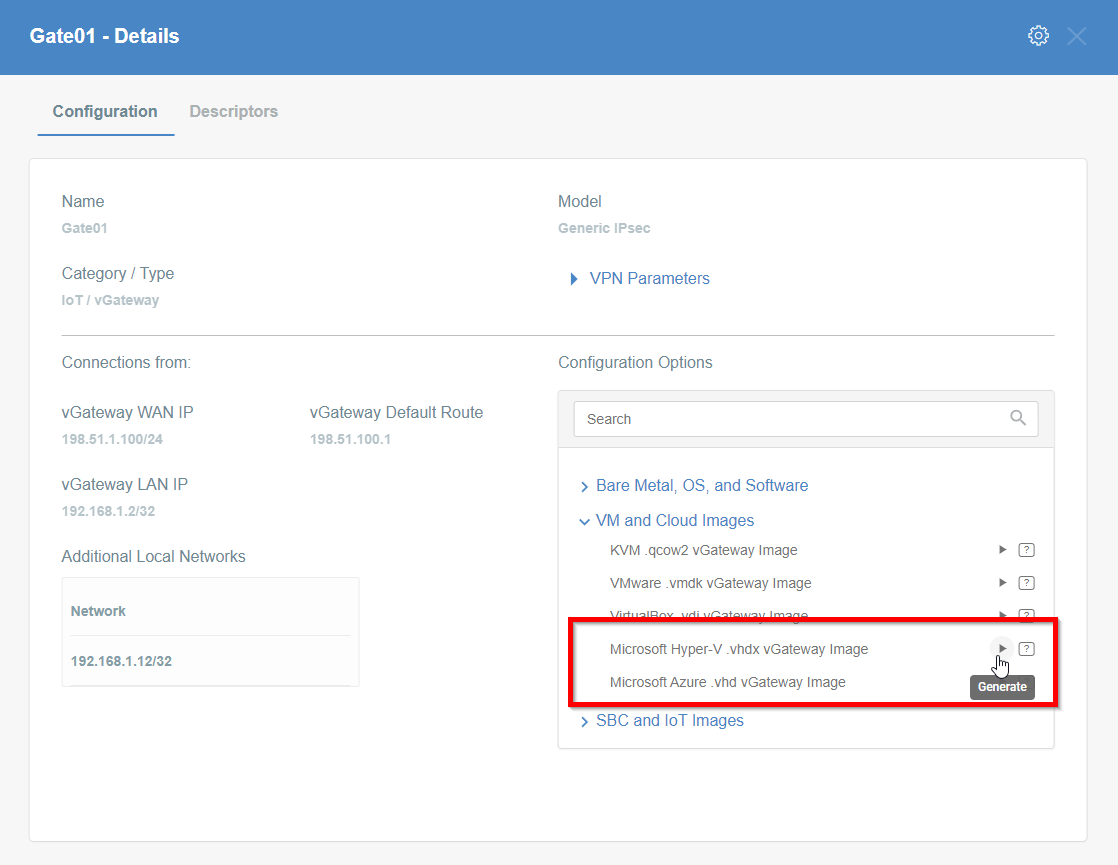
- When the image will be ready you may download it or copy the URL - save it on your Windows Server machine.
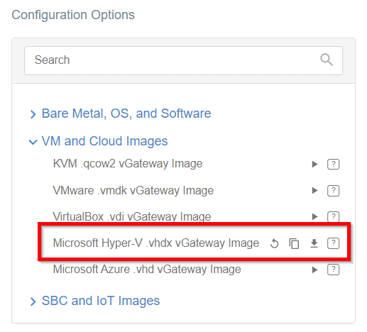
vGateway image installation
Adding the Hyper-V role to your Windows Server
Hyper-V feature is disabled by default in Windows Server. If you are sure that this option is already turned on on your machine you may skip this step.
To turn on Hyper-V on Windows Server:
- Log in to your Windows Server.
- Open the Server Manager Panel.
- Choose Add roles and features
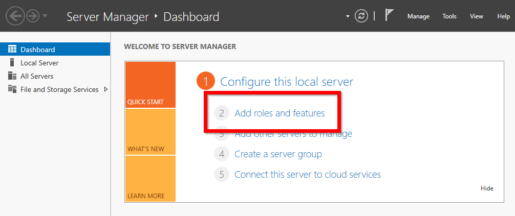
- Choose Role-based or feature-based installation and click on the Next button.
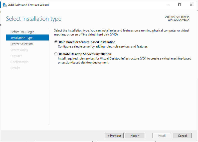
- Choose Select a server from the server pool and mark one on the list of available servers.
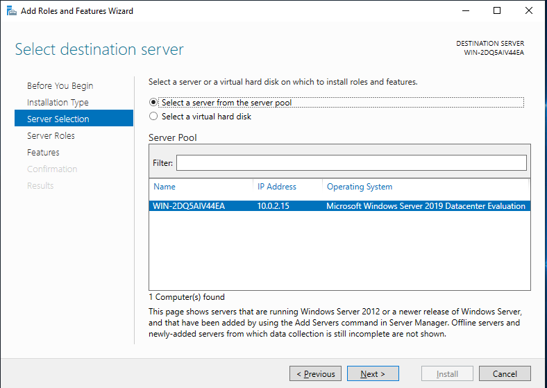
- On the list of the available roles search for Hyper-V, check this option and click on the Next button. If this option is already checked there’s no need to activate the Hyper-V option.
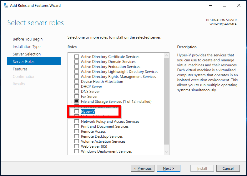
- On Hyper-V Virtual Switches screen choose the proper switch for your network configuration.
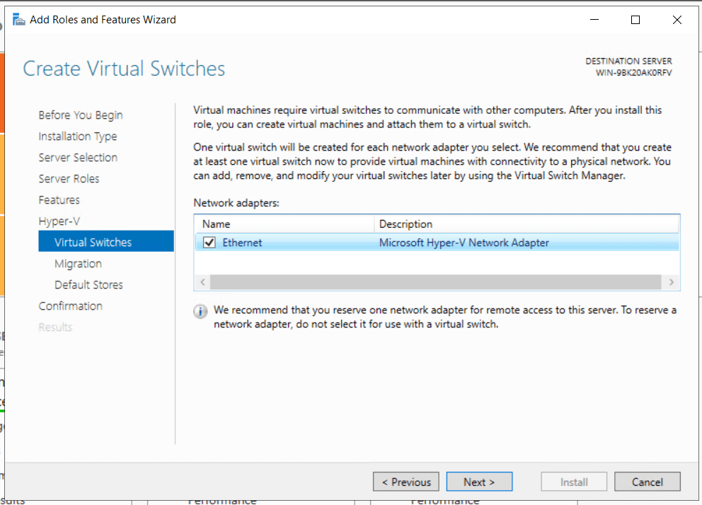
- Go thru the rest of the configuration screens.
- Restart the machine to finish Hyper-V Installation.
- After reset you should see Hyper-V in Roles and server groups.
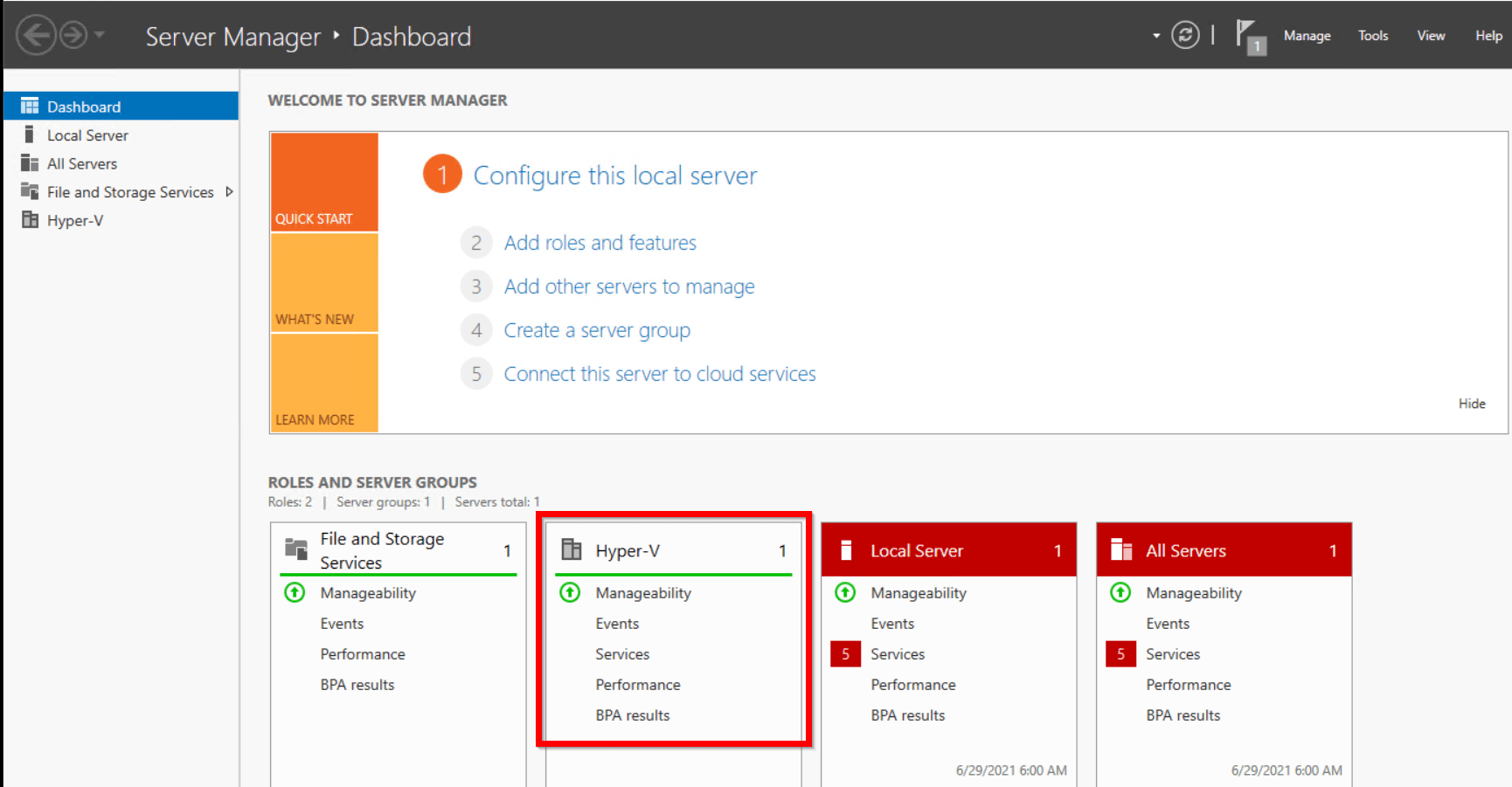
Install vGateway image
- Open Hyper-V Manager and select the New option to create a new virtual machine.
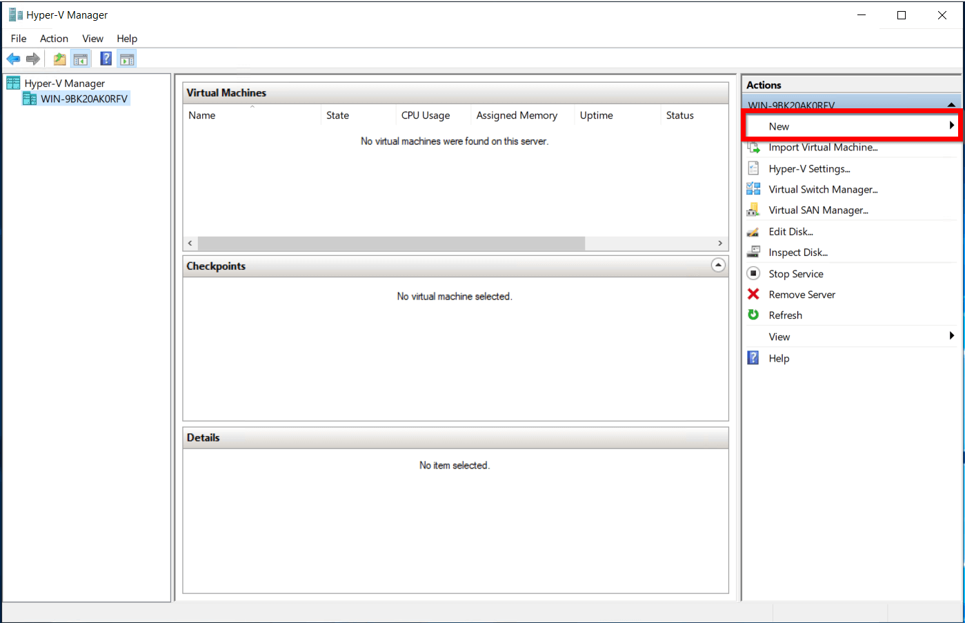
- On the Specify name and location screen call your new VM vGateway.
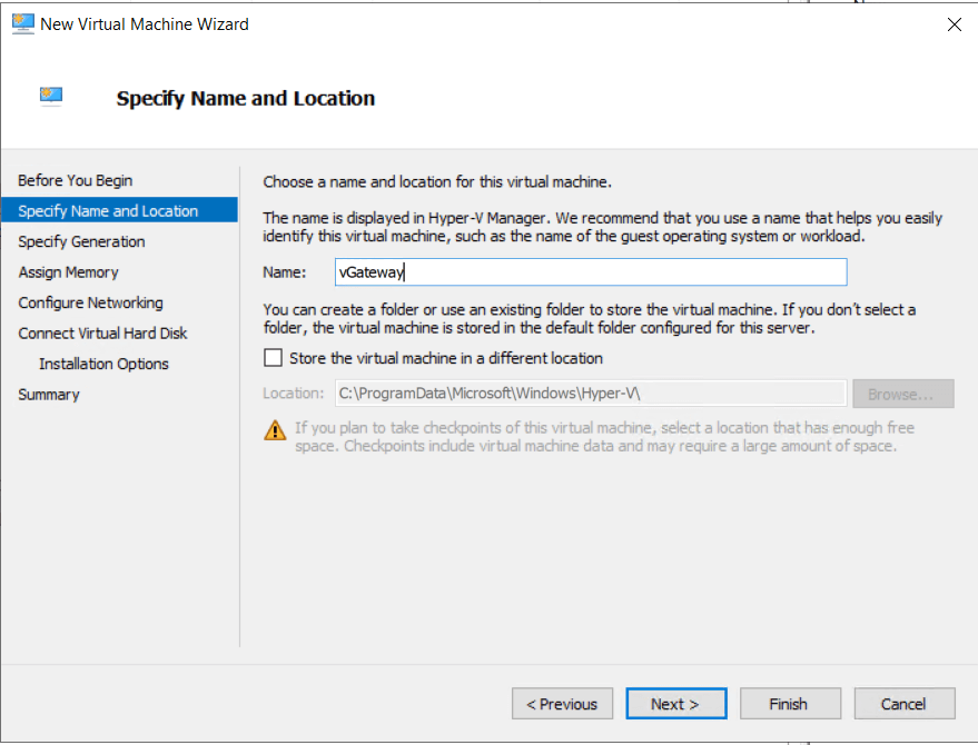
- On the Specify generation screen choose Generation 1
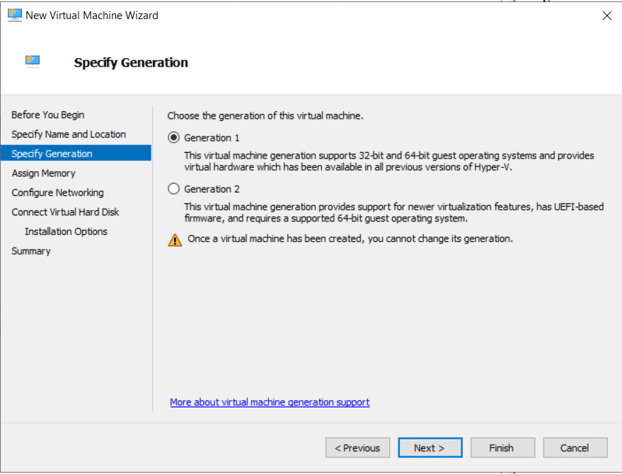
- On the Configure network screen connect VM to the proper interface.
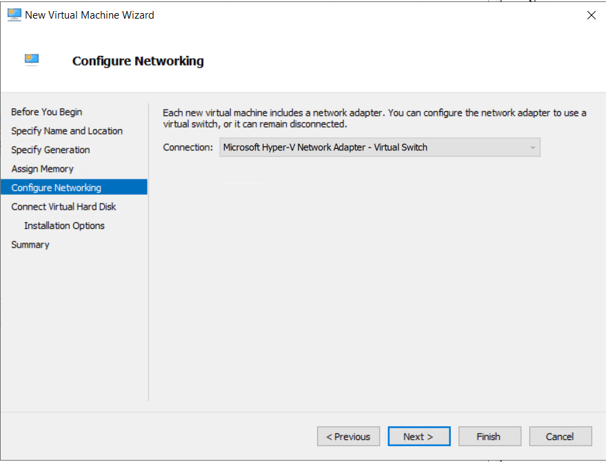
- On the Connect Virtual Hard Disc screen choose Use an existing hard disk and select downloaded vGatway image.
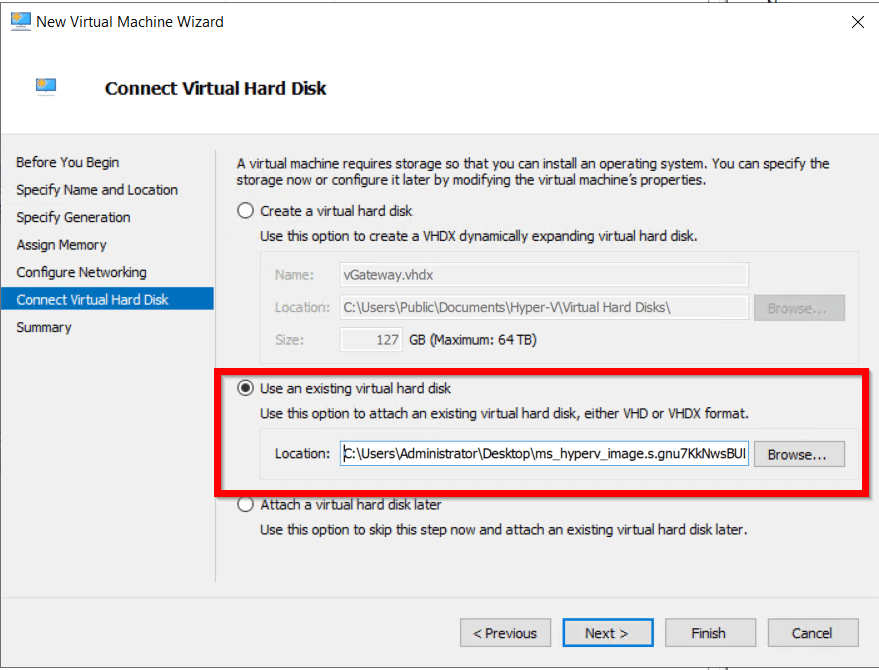
- Go thru the rest of the configuration steps and run the VM.
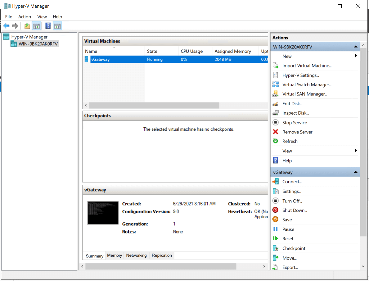
- Once the VM is up and running, you should be able to SSH to it with password authentication as:
- login: acreto
- password: acreto.io
- Change your password after the first login
Connectivity check
- Test the network connectivity
- IPsec status showing the tunnel status
ipsec statusall
- Traceroute to check if the traffic goes through Acreto Ecosystem
traceroute 8.8.8.8
- More information about checking the connectivity can be found under Connectivity Check the article where a dedicated tool is available.
Summary
Thanks to the Hyper-v technology you were able to install Acreto vGateway in just a few steps. Users can connect to an Acreto Ecosystem with the same credentials utilized for other internal resources on their network domain.
Also, Acreto Ecosystem Admin(s) can re-use any existing password and security policies that are already in place. For example, the Active Directory may already have account lockout and password expiration policies.
Introduction to vGateway
Overview
In this document, you’ll become familiar with the concepts and basic features of Acreto vGateway.
Functionality
Acreto vGateway is a software appliance that allows simple connectivity between branch offices, on-premise data centers, cloud platforms, and Acreto.

vGateway uses 2 network interfaces:
- WAN (usually the first interface on the device / VM) - used to communicate with the Internet.
- LAN (usually the second interface on the device / VM) - used to communicate with the local network.
vGateway acts as a gateway, allowing bidirectional communication between Acreto and the local network using an IPsec connection.
Devices (workstations, VMs, servers, etc.) in the local network should use vGateway’s LAN IP address as their default gateway. vGateway forwards traffic coming to its LAN interface to Acreto, and then sends traffic received from Acreto to its local destination.
Requirements
Acreto vGateway is supported on the following platforms:
- KVM (qcow2)
- VMware ESXi (.vmdk)
- VirtualBox (.vdi)
- Microsoft Hyper-V (.vhdx)
- Microsoft Azure (.vhd)
- Raspberry Pi 3 and 4
Network Connectivity

vGateway LAN interface should be connected to the LAN network. All devices in the LAN network should use vGateway as a default gateway.
vGateway WAN interface should be connected to the internet router.
Firewall
Acreto vGateway communicates with Acreto using IPv4 and IPsec protocol. To allow networking connectivity, the firewall needs to allow communication on the following ports and protocols:
- Protocol: UDP, ports: 500, 4500
- Protocol: ESP
You can find a list of IP networks used by Acreto on IPv4 and IPv6 subnets page.
NAT
Acreto vGateway can be installed behind NAT. However, if you are installing more than one vGateway behind the same NAT device, each of them must get a different public IP address.
In addition, the NAT device should have IPsec Passthrough enabled.
Example
In a deployment involving two vGateway devices (192.0.2.10, 192.0.2.11), the NAT device needs to have at least two public IP addresses (198.51.100.10, 198.51.100.11) and define Source NAT rules to assign a different public IP address to each vGateway. In this case:
- to vGateway 1 - 198.51.100.10
- to vGateway 2 - 198.51.100.11

Specification
- Base OS:
- Raspberry Pi version: Ubuntu 20.04 (LTS)
- Other platforms: Ubuntu 18.04.5 (LTS)
- Disk size (raw): 5400 MB
- Open ports:
- TCP 22 (SSH)
- UDP 500, UDP 4500 (ipsec)
Configuration
Web-based Configuration
The recommended way to configure Acreto vGateway is to modify configuration at https://wedge.acreto.net, and then generate and download a new image.
Manual Configuration
Acreto vGateway is a Linux-based solution. Administrators can connect and manage vGateways using SSH protocol and standard Linux tools. To get access credentials for your vGateway, please contact support.
Warning
vGateways with configuration modified by administrators might not be supported by Acreto.
The network configuration of Acreto vGateway is implemented using Netplan configuration files, placed in /etc/netplan. Refer to the Netplan website for more information.
IPsec connections are established using a Strongswan ipsec.conf configuration format, placed in /etc/ipsec.d/*.conf on the vGateway. The list of subnets that should be routed through Acreto is stored in /etc/ipsec.d/*.route files.
Alternatives
You can find other connectivity options on the Connect to the Acreto platform page.
Acreto vGateway uses OpenSource software that is part of Ubuntu Linux.
You can find more licensing information on the Ubuntu website, at https://ubuntu.com/licensing.
Troubleshooting - Unsupported or invalid disk error in ESXi
Error Description
Failed to power on virtual machine XXXXXX . Unsupported or invalid disk type 23 for ‘scsi0:1’. Ensure that the disk has been imported.

Cause
This issue occurs if a virtual machine that is meant for VMware Hosted products such as VMware Workstation, VMware Player or VMware Fusion is powered-on on an ESX/ESXi host.
The underlying format used to store virtual machines on VMware Hosted products differs from the format used to store virtual machines on ESX/ESXi hosts.
Solution
The .vmdk file needs to be converted to the accepted the ESXi format using the steps below:
-
Upload the .vmdk file to datastore in ESXi
-
Connect to the ESX/ESXi host via SSH
-
Run the below commands to convert the file
cd vmfs
cd volumes
cd datastore1
vmkfstools -i xxxxxx.vmdk xxxx-New.vmdk
Result
After successful conversion new file will be generated.
vGateway image installation on Azure
Overview
This article shows how to setup vGateway on Azure to connect your
network to Acreto Ecosystem.
Create new Gateway
To set up the vGateway on Azure first it is needed to configure the
Gateway object.
Please follow the steps in Gateway creation guide with the vGateway as a type of a gateway.
Generate Azure .vhd type vGateway Image
To generate an Azure the image you need to:
- In the Elements > Objects > Gateways menu click on the specified vGateway name - the details panel will appear.
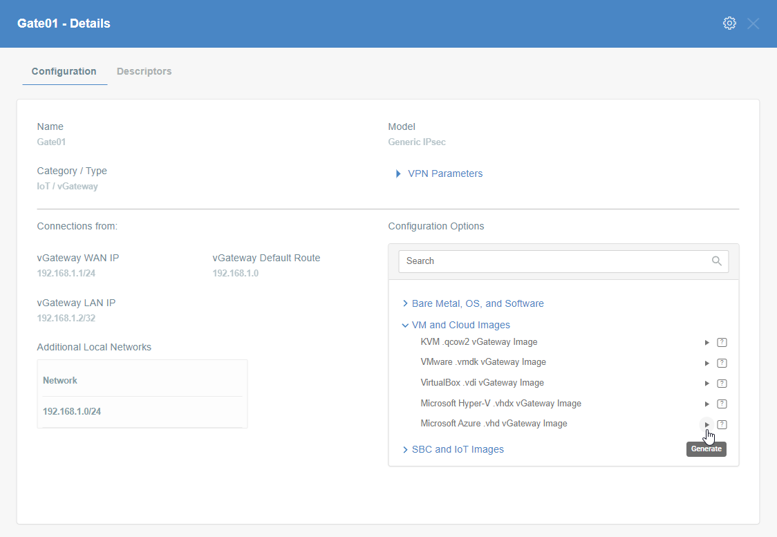
- On the right side of the gateway details panel click on VM and Cloud Images images to show a list of options to generate images.
- Click the play icon next to the Microsoft Azure .vhd vGateway Image entry.
- The generation of the image may take a while, please be patient.
- When the image will be ready you may download it or copy the URL - save it on your PC.
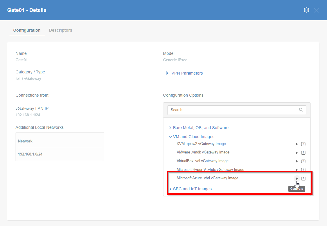
Image installation
To install the generated vhd image on Azure we need to proceed with uploading the image to Azure according to official documentation.
-
Create an empty managed disk on Azure.
-
Upload a vhd image to empty managed disk.
-
Start the VM with the uploaded image.
-
Once the VM is up and running, you should be able to SSH to it with password authentication as:
- login:
acreto
- password:
acreto.io
-
Change your password after the first login
-
Test the network connectivity
More information about checking the connectivity can be found under
Connectivity Check
the article where a dedicated tool is available.
vGateway image installation on VirtualBox
Overview
This article shows how to set up vGateway on VirtualBox to connect your network to Acreto Ecosystem.
Create new Gateway
To set up the vGateway on VirtualBox first it is needed to configure the Gateway object.
Please follow the steps in Gateway creation guide with the vGateway as a type of a gateway.
Generate VirtualBox .vid type vGateway Image
To generate a VirtualBox vid image you need to:
- In the Elements > Objects > Gateways menu click on the specified vGateway name - the details panel will appear.
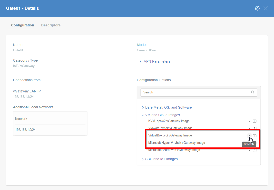
- On the right side of the gateway details panel click on VM and Cloud Images images to show a list of options to generate images.
- Click the play icon next to the VirtualBox .vdi vGateway Image entry.
- The generation of the image may take a while, please be patient.
- When the image will be ready you may download it or copy the URL - save it on your PC.

Image installation
To install the generated vdi image we need a machine with a VirtualBox hypervisor installed.
-
Create a new VM from vdi image by opening the Machine > New menu.
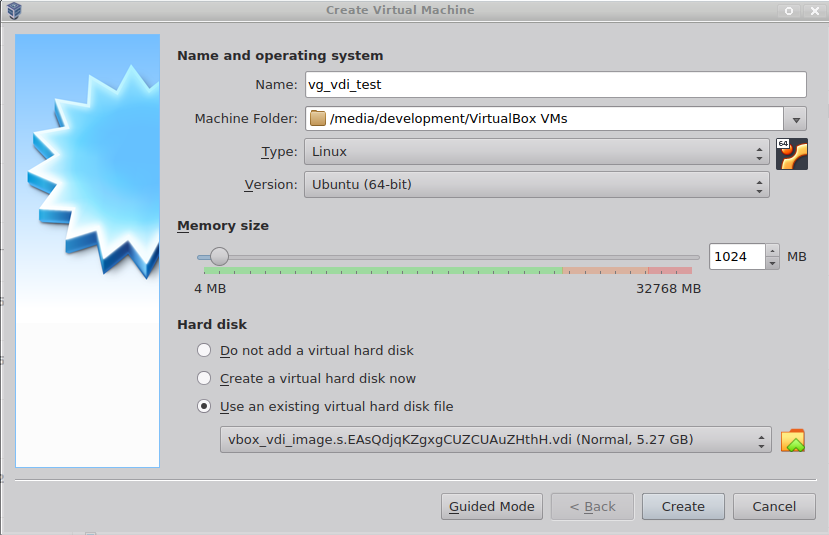
- In Type choose Linux.
- In Version choose Ubuntu (64-bit).
- In Hard disk choose Use an existing virtual hard disk file and select previously downloaded vdi image.
-
Start the VM.
- Ensure Acreto Ecosystem is routable from the hypervisor network.
- Enable a second network interface in the machine settings Network section.
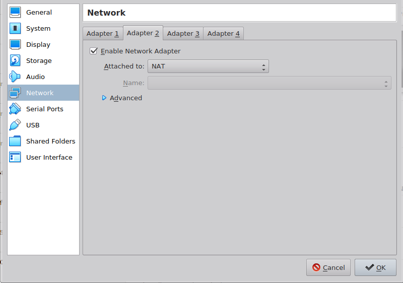
- Run the VM.
-
Once booted log in as:
- login:
acreto
- password:
acreto.io
-
Change your password after the first login
-
Test the network connectivity
More information about checking the connectivity can be found under Connectivity Check article where a dedicated tool is available.
vGateway installation on RasbperryPi
Overview
This article explains how to set up a vGateway on Raspberry Pi to connect your network to an Acreto Ecosystem.
Create New Gateway
To set up the vGateway on Raspberry Pi, you must first configure the Gateway object.

Please follow the steps below to create and configure a new Gateway that will be used as vGateway.
- Log in to the Acreto Portal at wedge.acreto.net.
- Select your Ecosystem and go to Objects using the left-side menu.
- Click Add new Object and select Gateway.
- Fill in the following fields:
- Name: the name of the gateway
- Category: IoT
- vGateway: select Gateway in the upper right corner
- DHCP/Static: Select DHCP
- vGateway Local IP: IP address of Raspberry Pi device in your LAN, i.e
192.168.200.1/24
- Local Networks: your local network addresses that will be routed through this gateway
- Save the created Gateway by pressing Add.
- Add a security policy that will allow communication from the Gateway device to the Internet.
- Commit pending changes (located at top of the screen).
Tip
To simplify testing, add the IP addresses of every interface connected to your gateway as Local Networks (you can use /32 prefix for public interface). This will allow testing connectivity from the gateway through Acreto using Ping, Traceroute, or similar tools.
Note
To successfully test your connectivity, you also need to create a security policy that will allow traffic to go through your device.
Generate Raspberry Pi vGateway Image
To proceed with this step, you should have at least one Gateway configured as vGateway in your Ecosystem. From the left-side menu, select Objects > Gateways to display the list of existing gateways.
To generate a Raspberry Pi configuration image, you must:
- Click on the vGateway name on the vGateway panel. The details panel will then appear.
- On the right side of the gateway details panel, click on SBC and IoT Images to view a list of image generation options.
- Click the play icon for the right version of the device.
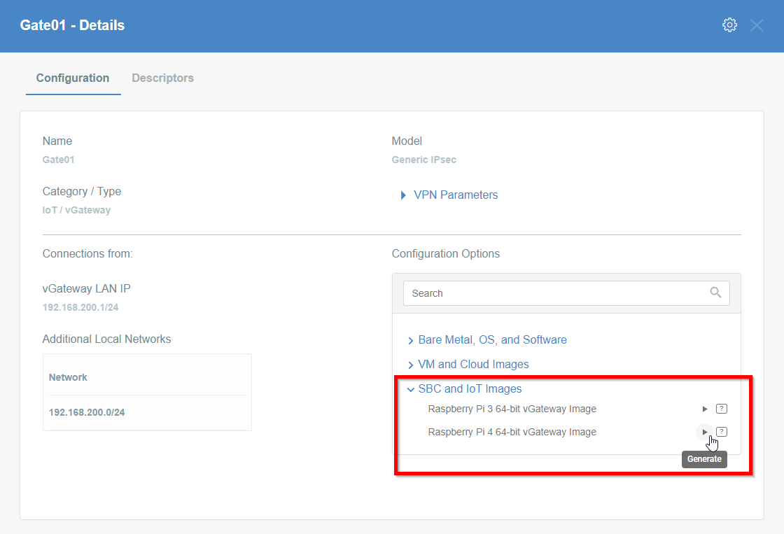
- The generation of the image may take a while, please be patient.
- When the image is ready, you may download it or copy the URL & save it on your PC.
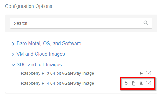
Image Installation
Linux
To proceed with this step, you must have an image file generated by Acreto or a URL to the image for your vGateway.
To install the image, you must first proceed with flashing the SD card.
-
Download the write_image.sh script.
Click on the button and save the script in your home directory:
Get write_image.sh
or open the terminal and download the script using the command:
wget https://kb.acreto.net/reference-material/downloads/write_image.sh
-
Take the SD card out of your Raspberry Pi device.
-
Insert the SD card into your computer.
- Ensure it doesn’t mount automatically - if it does, unmount it.
-
Use the write_image.sh script to write the image onto the SD card.
-
if you have an image file downloaded locally:
./write_image.sh image-file.zip /dev/sdb
-
if you want to use the URL of an image directly:
./write_image.sh https://aws1-vgateway-images.s3.amazonaws.com/vgateway-raspberry-pi4.s.nAH2xOL8HyJIK1g8v4HEsNCt.img.zip /dev/sdb
where /dev/sdb is the location of your SD card
-
Once finished, take the SD card from your computer and plug it into your device.
-
Restart the Raspberry device and wait until it boots from the SD Card.
-
Log in to your WEDGE account.
-
From the left menu choose the Logs > Gateways option.
-
As one of the last inputs, you should see information about the established connection from your Gateway.
More information about checking the connectivity can be found in the Connectivity Check article, where a dedicated tool is available.
Windows
To proceed with this step, you must have an image file generated by Acreto.
-
Take the SD card out of your Raspberry Pi device.
-
Insert the SD card into your computer, wait until it is visible in the system.
-
Unzip the file downloaded from WEDGE, make sure that you can see the *.img file.
-
Go to Raspberry Pi Software Page.
-
Download the last version of Raspberry Pi Imager.
-
Run downloaded *.exe file and install it.
-
If Raspberry Pi Imager doesn’t start after installation, run it manually. You should see the window presented below:
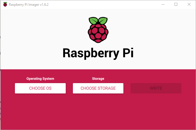
-
Click on the Choose OS button and select the Use custom option.
-
Select a downloaded image using the explorer window.
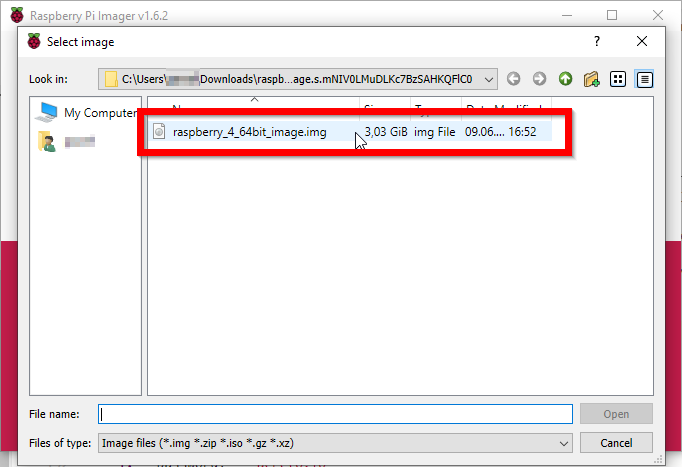
-
Click on the Select Storage button and choose your SD Card.
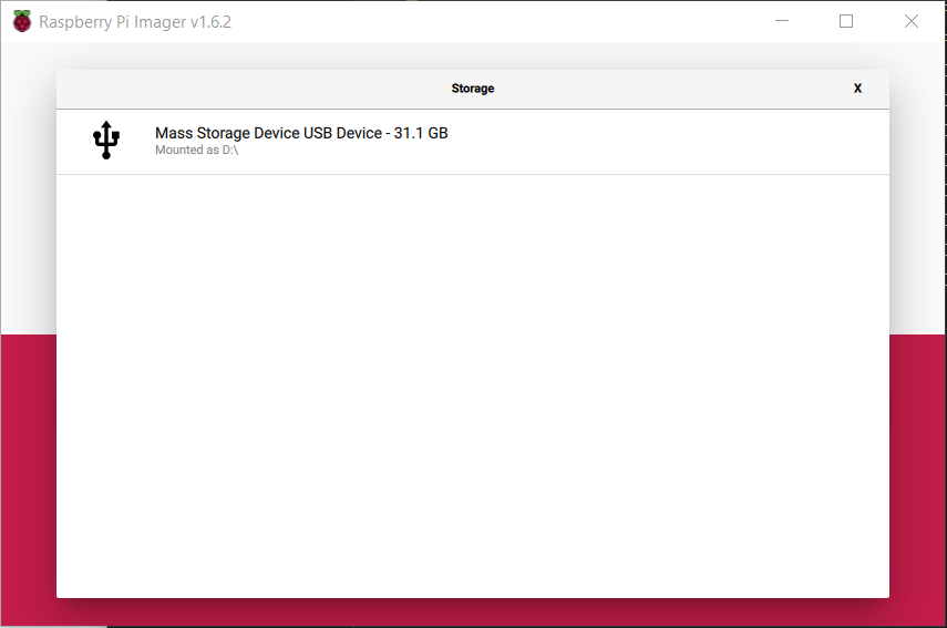
-
Double-check the settings and if they’re OK, click on the Write button.
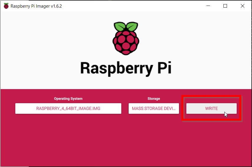
-
The writer will warn you about erasing the current content of the SD Card, click on the YES button to continue.
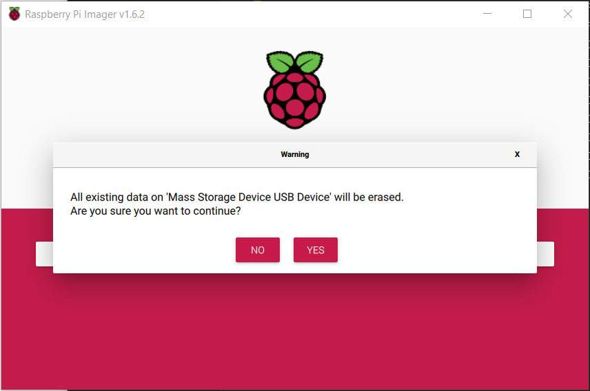 Now the Writing process will start, it may take a few minutes.
-
When writing ends, you should see the below information.
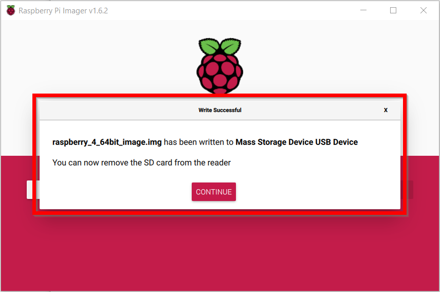
-
Once finished, take the SD card from your computer and plug it into your device.
-
Restart the Raspberry device and wait until it boots from the SD Card.
-
Log in to your WEDGE account.
-
From the left menu choose the Logs > Gateways option.
-
As one of the last inputs, you should see information about the established connection from your Gateway.


More information about checking the connectivity can be found in the Connectivity Check article, where a dedicated tool is available.
List of Supported USB Ethernet Adapters to Use for LAN
By default, the Raspberry Pi has only one Ethernet adapter. But to connect your network, you’ll need an additional Ethernet adapter.
Acreto recommends using a USB Ethernet dongle facing the LAN network.
Show the list of supported USB Ethernet devices
USB Ethernet Adapters Officially Supported by Acreto
- TP-Link
- TP-Link UE300 USB 3.0 to Gigabit Ethernet Network Adapter.
- Works out of the box on Raspbian Wheezy on a Pi 2 Model B.
- No external power source or USB hub needed.
- Pi is powered by a 2.5 amp power supply.
Other Raspberry Pi Supported USB Ethernet Adapters
Other devices:
Warning!
Please note that this is a list of USB Ethernet adapters confirmed to work by the Raspberry Pi Community. None of the devices below were tested by Acreto.
- ADMtek
- ADM8511 Pegasus II Ethernet, full-speed, idVendor=07a6, idProduct=8511:
- Works out of the box. No external power source needed.
- AVM
- FRITZ!Box WLAN 3030 USB Ethernet Adapter: Works out of the box.
- No external power source needed.
- ASUS
- USB 2.0 to Fast Ethernet Adapter (ASIX AX88772B)
- USB Ethernet Adapter: As distributed with Zenbook Ultrabooks.
- Works out of the box.
- No external power source needed.
- Cable Matters
- USB 3.0 to Gigabit Ethernet Adapter (ASIX AX88179) USB Ethernet Adapter.
- NOTE: Since Raspbian 3.8.y kernel does not include a driver for this hardware, you must build a new kernel module from the source code provided by ASIX here.
- Easy to follow instructions on how to download the kernel source code and symbol files can be found in the second posting here, including how to compile the module.
- For Raspbian 3.9.+ the driver is already included in the distribution.
- Wintech
- USB 2.0 LanCard Model: LAU-15 (CK0049C) using the mcs7830 driver.
- Probably needs more than 100 mA current. [1]
- LogiLink
- USB 2.0 UA0144: AX88772 chipset using the ASIX kernel driver.
- Does not work without a powered USB hub. (idVendor=0b95, idProduct=772b)
- LogiLink Fast EN USB 2.0 to RJ45 Adapter: Test on Wheezy-Raspian
- (2012-08-16) without USB Hub will be confirmed
- lsusb output: Bus 001 Device 004: ID 9710:7830 MosChip
Semiconductor MCS7830 10/100 Mbps Ethernet adapter
- BE CAREFUL: There exists a copied Chinese version without the
Logilink logo using the Kontron DM9601-chip (see “Problem Ethernet
adapters” below). This only supports USB1.1 and isn’t well-supported in
Linux. If you get a model without the Logilink logo and the model number
JP1082, it’s a fake.
- Apple
- Apple USB Ethernet Adapter using ASIX kernel driver.
- Works out of the box (driver present since kernel 2.6.32).
- Doing OK using Apple USB charger and Pi’s own USB port.
- USB register states that it draws max. 250 mA.
- Belkin
- USB 2.0 Ethernet Adapter (F4U047)
- Works out of the box without any needed setup.
- No powered USB hub needed, tested on Raspberry Pi A+.
- Edimax
- Edimax EU-4208 USB2.0 Fast Ethernet Adapter
- (idVendor=0b95, idProduct=772b)
- Works out of the box.
- Requires own power supply (from powered USB hub).
- Edimax EU-4230 USB2.0 Fast Ethernet Adapter with 3 port USB hub
- Works out of the box.
- Requires own power source.
- D-Link
- D-Link DUB-E100 Fast Ethernet USB 2.0 Adapter
- Works out of the box.
- Requires own power supply (from powered USB hub).
- LinkSys
- LinkSys - USB200M - Compact USB 2.0 10/100 Network Adapter
- Raspbian recognizes it automatically.
- Tested on a powered USB hub.
- Linksys - USB300M - Compact USB 2.0 10/100 Network Adapter
- Works out of the box.
- Doesn’t require powered hub when powering Pi using MicroUSB supply
rated for 0.7A output.
- Linksys - USB3GIG v1 (Vendor ID: 13b1, Product ID: 0041)
- USB 3.0 gigabit adapter
- Works very well on a Raspberry Pi 2 running Raspbian 2015-02-16.
- Faster than the built-in adapter, connects at gigabit rate.
- iperf tests show about 150 - 175 Mbit speed.
- Pluscom
- Pluscom U1EC
- Davicom DM9000E chipset
- DM9601 driver
- Max current 144mA
- Unlike later ( what is later? ), USB 1.1 devices using the same driver
- Pluscom U2E-ADM8515
- ADMtek, Inc. AN8515 Ethernet chipset
- Pegasus driver
- Max current 224 mA
- Works with a Model “A” Pi if plugged into an external
(maybe unpowered) hub.
- Sabrent
- Sabrent USB 2.0 10/100 Ethernet Adapter
- Works out of the box (ASIX).
- USB 2.0 only
- (Does not work if using dwc_otg.speed=1 in cmdline.txt to force USB 1.1
for other problem hardware)
- Sitecom
- Sitecom LN-030 V2 detected as ASIX AX88772 USB 2.0
- Ethernet Adapter works out of the box.
- Doesn’t seem to require any extra power supply.
- TrendNet
- Trendnet TU2-ET100 Adapter works out of the box.
- Trendnet TU3-ETG Gigabit USB 3.0 Adapter works out of the box.
- Works well on a Raspberry Pi 2 running OSMC Release Candidate.
- SMB test shows approx 150mpbs.
- Hama
- Hama 00049244 Fast Ethernet USB 2.0-Adapter
- Detected as MOSCHIP 7830/7832/7730 usb-NET adapter.
- Works out of the box on Debian Wheezy/sid (2012-08-08-wheezy-armel).
- (Not tested yet on other OS).
- No external power source or USB hub needed.
- Newlink
- Newlink NLUSB2-ETH USB 2.0 Ethernet Adapter
- Works out of the box on Raspbian.
- Detected as ASIX AX88772.
- ASix driver
- Max current 250mA
- Works without a powered hub or when plugged into an unpowered hub.
- Axago
- Axago ADE-X1 10/100 Ethernet Adapter (USB: 9710:7830 driver:mcs7830)
- Adapter needs the last Raspbian kernel.
- With older kernels the adapter works about 10 minutes without a problem,
but after that, the kernel writes an error message to dmesg and no packet is received. Must unplug and plug USB again.
- Tested with and without a powered USB hub.
- i-tec
- i-tec USB 2.0 Ethernet Adapter Fast Ethernet (chip ASIX AX88772B)
- Works out of the box very stable with ASIX kernel driver on latest Raspbian
3.6.11+ (Nov. 2013), Raspberry Pi model B, 256MB RAM.
- Connected through a powered USB hub (may work without it, not tested).
- lsusb output: Bus 001 Device 005: ID 0b95:772b ASIX Electronics Corp.
- Plugable
- Plugable USB2-E100 USB 2.0 10/100 Ethernet adapter
- Works out of the box.
- (ASIX AX88772 chipset)
- Raspberry Pi reboots when you plug it into the USB port,
but after that it works fine.
References
Subsections of Open VPN connection
Connect GL.iNet using OpenVPN client
Overview
In this article, you’ll learn how to set up an OpenVPN client on Gl.iNet and connect it to the Acreto ecosystem.
How to
Prerequisites
To connect GL.iNet router with Acreto Ecosystem, you will need:
-
Existing Acreto Ecosystem, if you don’t have one learn how to create it.
-
Access to Acreto Wedge.
-
GL.inet router with OpenVPN client installed.
Download the VPN profile from Acreto
-
Log in to the Acreto Portal.
-
Choose your Ecosystem.
-
Create a new VPN profile using tutorial or use the existing profile.
-
Download the Acreto VPN profile
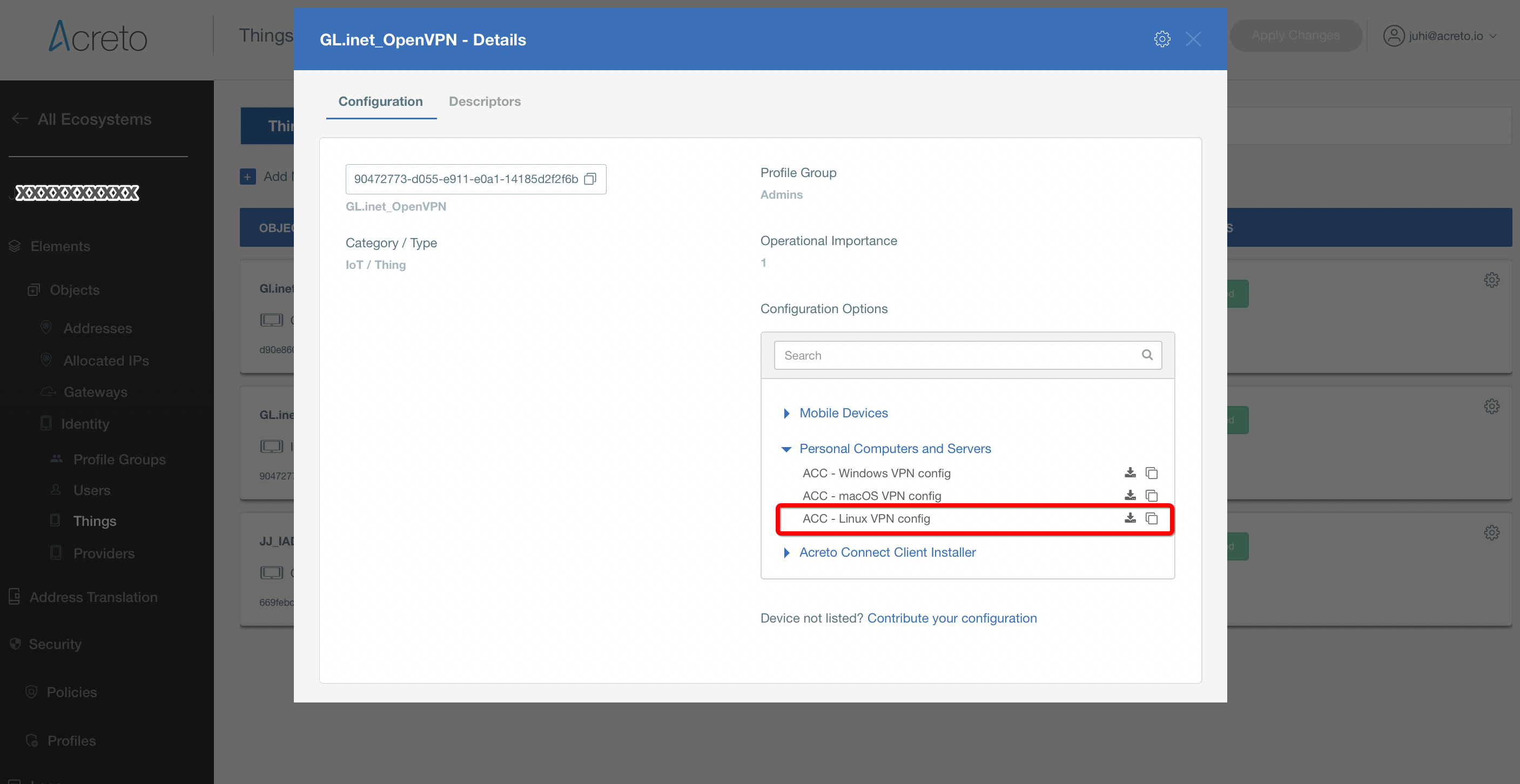
Setup OpenVPN client on GL.iNet
-
Login to the GL.iNet routers Web Admin Panel.
-
From the left sidebar, goto VPN » OpenVPN Client and click Add a New OpenVPN Configuration.
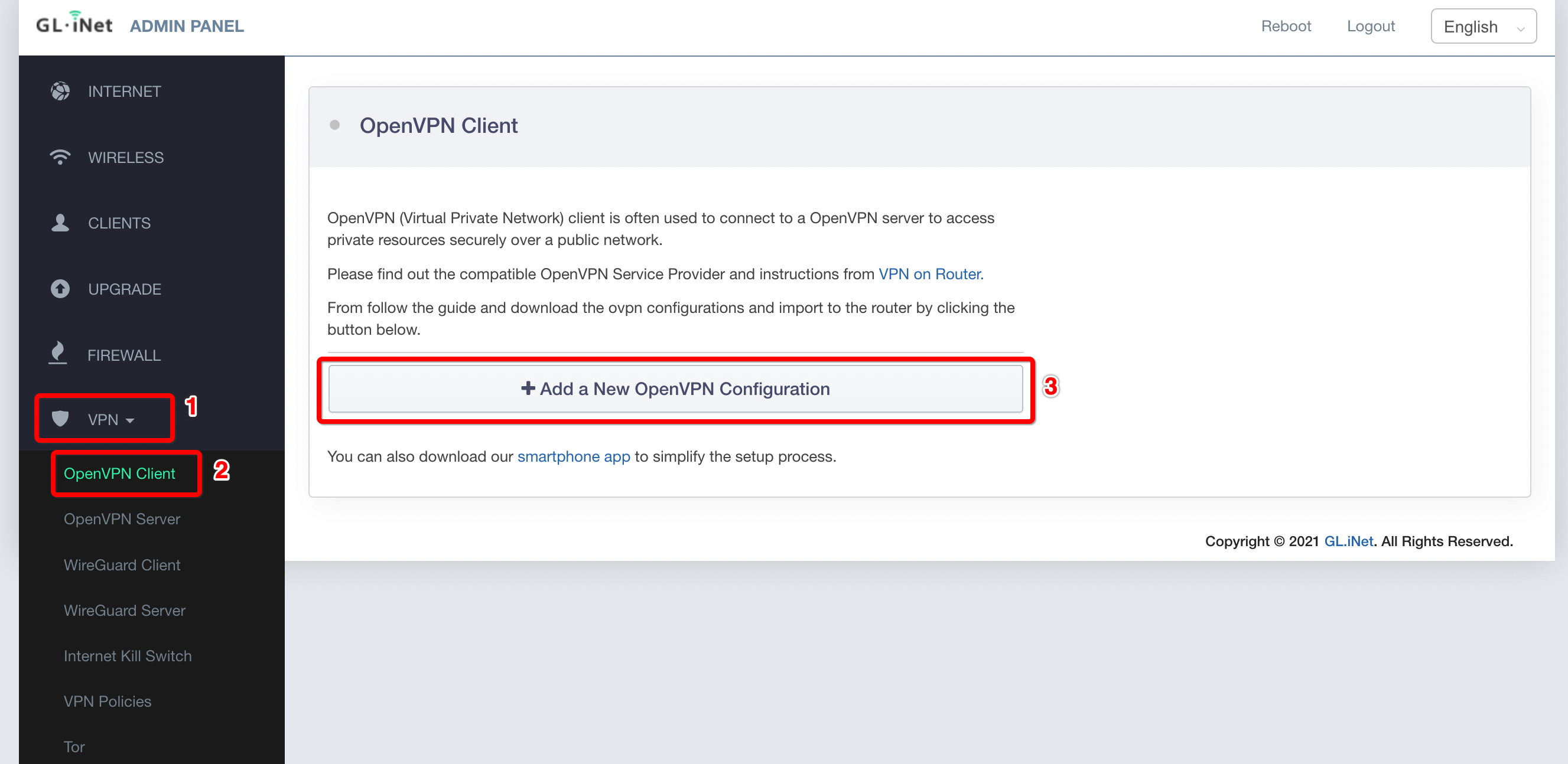
-
Add a new OpenVPN configuration.
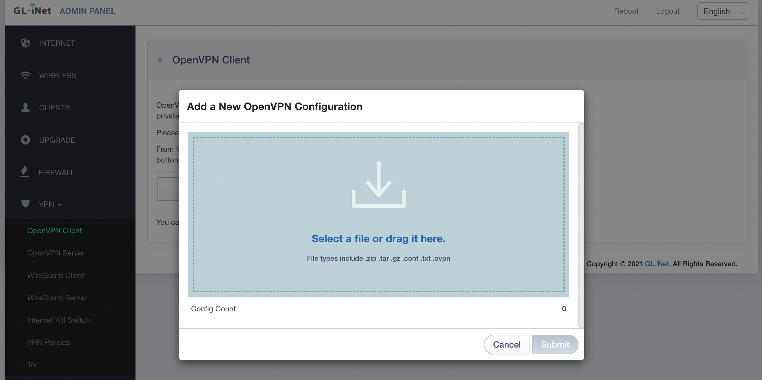
-
Upload your VPN configuration file from Acreto.
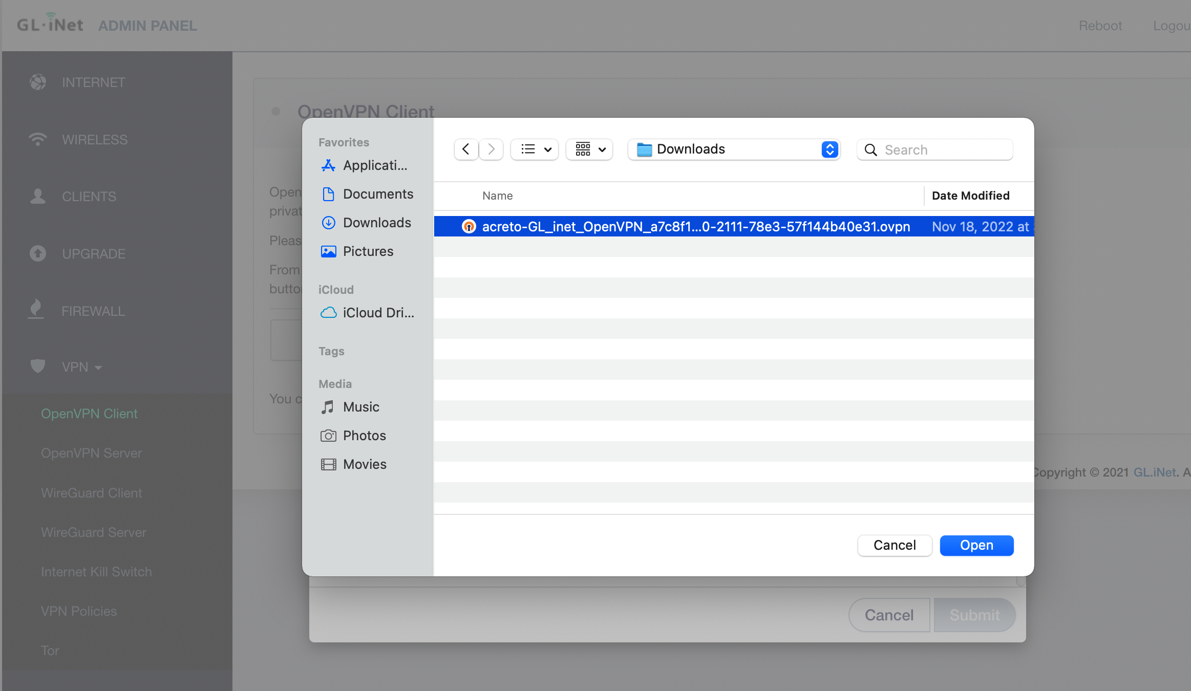
-
Enter a description for your VPN configuration file and then click Submit to finish the upload process.
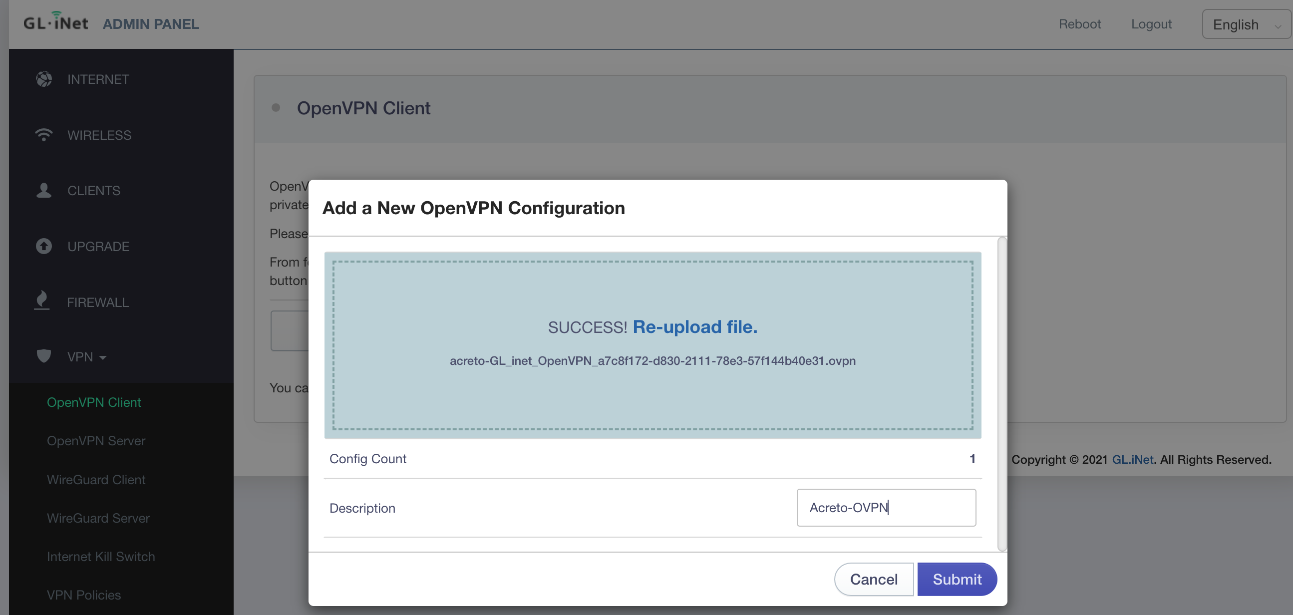
-
Click Connect to start the VPN connection.
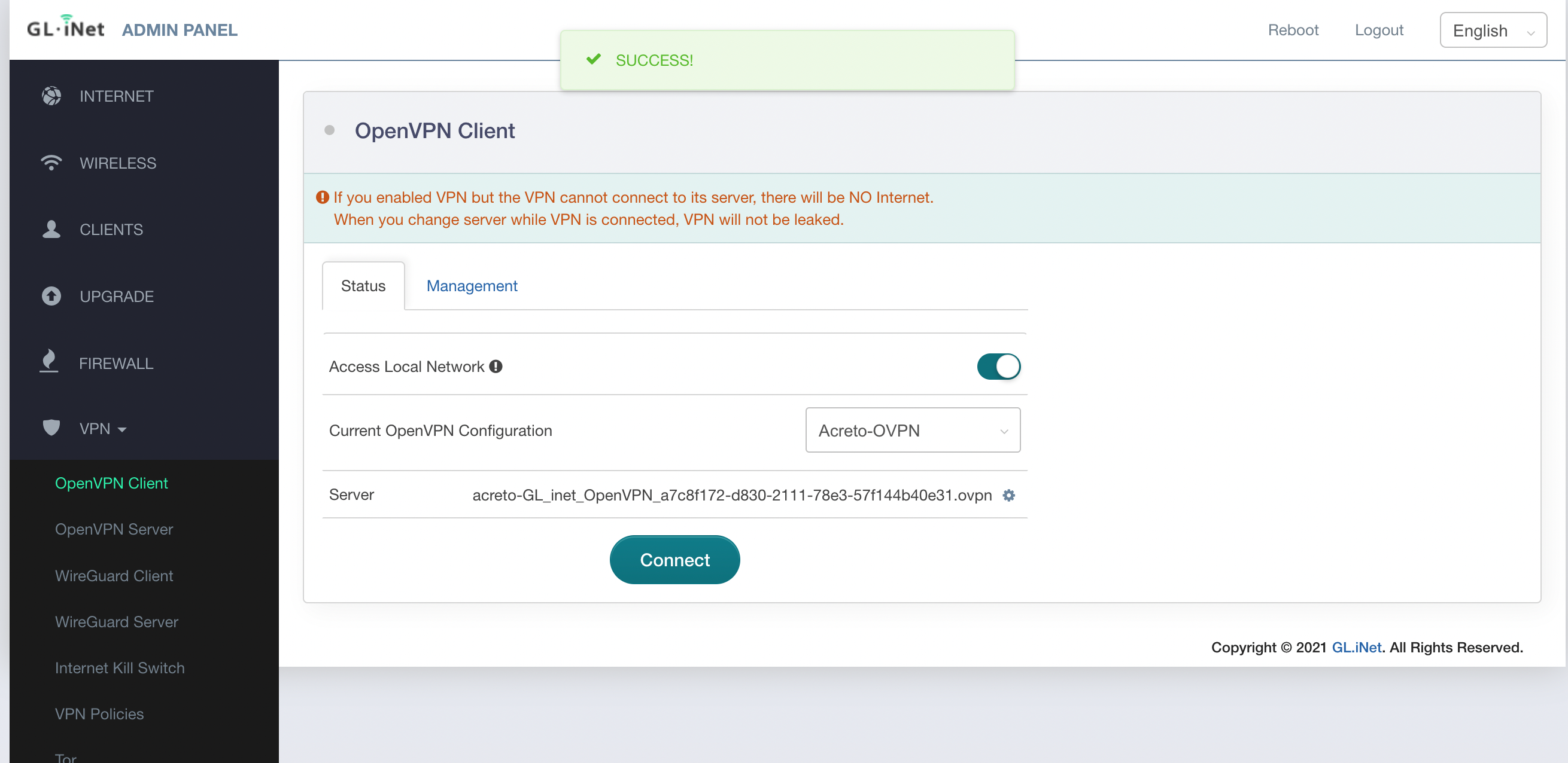
-
Once connected, the Disconnect button is shown on the screen along with the recieved IP address and Data sent and recieved information.
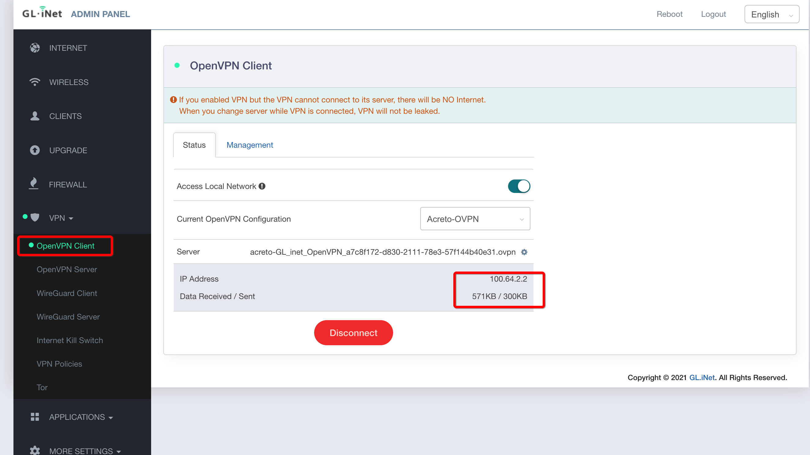
-
At this point, the machine is connected to Acreto Ecosystem. You may confirm that by checking logs available in Acreto Acreto Portal > Logs > User and Things.
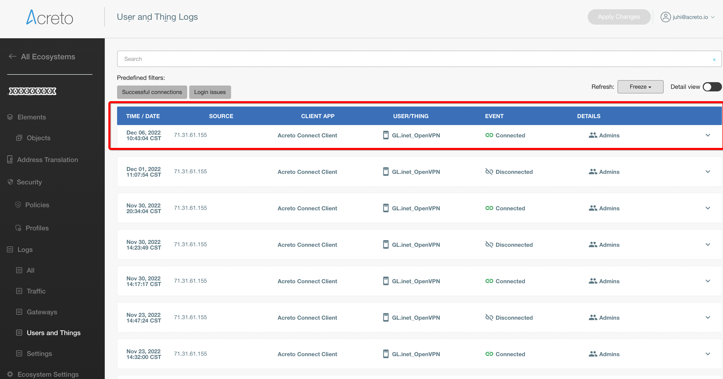
Android
Overview
This guide will help you to configure the Acreto Security connection on your Android device with the help of the OpenVPN app.
Android
Android doesn’t have built-in OpenVPN support. It is required to download
OpenVPN app from Google Play store.
1. Go to the Google Play Store

2. Search for the OpenVPN Connect application

3. Install the OpenVPN Connect application

4. Once the application is installed, download the configuration
Open the https://wedge.acreto.net in your favorite browser.
Add a thing named laptop on Acreto Ecosystem - check how to do it

Open the laptop thing details:

Click on Download OpenVPN config file to save the configuration.

5. Launch the application from your home screen or menu
On the following window, select FILE tab.

6. A similar permissions prompt window should be received

7. Click Allow and navigate to the folder with OpenVPN config file

By default, it should be in the downloads folder.

Make sure that OVPN is selected (see image below), then select the files you want to import and press IMPORT button on the upper-right corner.

8. Enter any title for the connection

Select Connect after import
Then press the Add button.
9. When asked for permissions

Click the OK button.
10. When prompt for a certificate
Click on Continue button.
11. The connection is successful
The connection stats window should be visible.
There you can see extensive information about your connection, such as current data throughput or duration.

12. To disconnect
Simply press the switch button next to the OpenVPN profile name and toggle it off.
iOS
Overview
This guide will help you to configure the Acreto Security connection on your Apple mobile device with the help of the OpenVPN app.
iOS
1. Go to the App Store on your iPad/iPhone

2. Enter OpenVPN connect in the search bar

3. Tap on the GET button

4. Once the application is installed, download the configuration
Open the https://wedge.acreto.net in your favorite browser.
Add a thing named laptop on Acreto Ecosystem - check how to do it

Open the laptop thing details:

Click on Download OpenVPN config file to save the configuration.

5. Launch the application from your home screen or menu
Select whether you wish to enable push notifications.

Accept the OpenVPN Policy Agreement
6. Go to home screen and open Files
7. Navigate to the folder with OpenVPN config file

Select the Share button in the upper right-hand corner.

Press Copy to OpenVPN

8. Add the VPN profile
Ensure the OpenVPN profile selected is correct, then press ADD.

9. Name the connection
Feel free to specify the profile name, by changing the field

Be sure to check the box Connect after import

10. When asked for permissions
Click Allow to allow OpenVPN to add VPN connections.

Click Yes to allow OpenVPN to enable the VPN connection.

If all went well, you should see the following

11. To disconnect
Tap on the same button you used to connect.
Linux
Overview
This article will demonstrate how to secure your Ubuntu system with an Acreto Secured Connection. To create an additional layer of security, we’ll use the OpenVPN application.
Before proceeding to the installation, make sure that you’ve added at least one Thing to your Ecosystem - if not, check how to do it.
Solution 1: Script-based Installation
Acreto Wedge offers a ready-to-use script that will install and configure the Acreto client on your Ubuntu system:
- Log in to your account on Acreto Wedge.
- Select the Ecosystem where your device is configured.
- Click on the Objects item from the left side menu.
- Find your Ubuntu device on the list and click the i button to show the details panel.
- Within the details panel, you’ll see a Configuration Options section with a list of ready-to-use configurations. Find Acreto Connect Client for Ubuntu 18.04 LTS on this list and click the download icon.

- Run this downloaded script – acreto-connect.sh.
Once the script finishes downloading your device should be connected to Acreto.
What does the script do ?
The script:
- Checks the type and version of the Operating System
- Installs OpenVPN and all other required dependencies
- Pulls the TLS-client configuration via API call using the device token
- Creates a service enabled at boot
- Starts the service and connects the client to the Acreto platform
In case the TLS client is already installed,
the user is presented with a menu to update/remove it.
Solution 2: Manual Installation
Don’t want to manage the VPN setup automatically?
How to connect to OpenVPN manually using the terminal:
- Open the Terminal (keyboard shortcut:
ctrl + alt + t).
- Install OpenVPN client by entering:
sudo apt-get install openvpn
- Navigate to the OpenVPN configuration directory with this command:
- Download OpenVPN configuration files –
in the terminal, type command:
curl -k --silent --request POST -H 'Accept: text/plain' \
https://api-is-rock-solid.acreto.net/v2/tlsvpn/config?_token=SECRET
sudo apt-get install ca-certificates
- Start OpenVPN with a chosen configuration by entering:
For example:
- You have successfully connected to the VPN!
- To disconnect, open the terminal window it’s running in and press
ctrl + c.
MacOS
Overview
This article will show you how to secure your MacOS device with Acreto Secured Connection. To create an additional layer of security we will use the Tunnelblick app.
Configuring MacOS
The Tunnelblick application is a recommended option for connecting to ACRETO
servers on your Mac.
1. Download the Tunnelblick
Tunnelblick provides free, user-friendly control of OpenVPN client connections for macOS.
2. Download the OpenVPN configuration
Add a thing named laptop on Acreto Ecosystem - check how to do it

Open the laptop thing details:

Save the file as-is, or change the name to acreto-thing.ovpn
3. To begin the installation of OpenVPN for macOS
Navigate to your Downloads folder and double-click the Tunnelblick image (DMg) file you just downloaded

4. Double-click on the Tunnelblick icon in the Tunnelblick disk image Finder window

5. A dialog box will appear
Tunnelblick is an app downloaded from the Internet. Are you sure you want to open it?
Click Open

6. The installer will ask for your password. Enter it and click OK:

7. After the installation completes, you will see a pop-up notification:
Installation succeeded. Tunnelblick was successfully installed.
Do you wish to launch Tunnelblick now?
(An administrator username and password will be required so Tunnelblick can be secured.).
Click Launch
8. Alternatively, you can click on the Tunnelblick icon on the status bar
and click VPN details:

9. A dialog box will appear:
There are no configurations installed.
Click I have configuration files

10. A pop-up will appear with instructions on how to import configuration files:

Click OK
11. Drag and drop the previously downloaded .ovpn file
From your Downloads folder, copy->paste or drag and drop to the Configurations tab on the Tunnelblick.

12. A new pop-up will appear
The Installer will ask if you want to install the configuration profile for your current user only, or for all users on your Mac.
Select your preferred option: [All Users] / [Cancel] / [Only Me]
13. You will be asked to enter your password again.
14. A new pop-up warning will appear about comp-lzo deprecation.
You can safely check the Do not warn about this again and click OK.
15. Select the server and click Connect.
16. You are connected to the VPN
17. Check your IP address
Browse to https://www.myip.com/ and verify your IP and network (should be different than your ISP).
18. Disconnect
Click on the Tunnelblick icon in your menu bar and select Disconnect from the drop-down menu.
Windows
Overview
This article will show you how to secure your Microsoft Windows with Acreto Secured Connection. To create an additional layer of security we will use the OpenVPN application.
Configuring Windows 10
Use these steps to set up a VPN on a computer running Windows 10.
You can set up a manual OpenVPN connection by using the OpenVPN application.
1. Download the OpenVPN GUI application
https://swupdate.openvpn.org/community/releases/openvpn-install-2.4.8-I602-Win10.exe
2. Open the installer file

3. Follow the setup wizard

4. Once the application is installed, download the configuration
Add a thing named laptop on Acreto Ecosystem - check how to do it
Open the laptop thing details:
Save the file as-is, or change the name to acreto-thing.ovpn
5. Go to the folder where the configurations are downloaded
6. Click and drag to select the OpenVPN configuration downloaded
7. Right-click on them and select Copy
8. Find the OpenVPN config folder
Right-click the OpenVPN GUI shortcut on your desktop and select
Open file location.

9. Once you’re there, click the parent OpenVPN folder in the address bar

10. Extract the configuration file you need to this directory:
c:/Program Files/OpenVPN/config
11. Open the OpenVPN config folder

12. Paste the copied configuration files in the folder

13. Click Continue to allow the files to be extracted to the folder

14. Note: How to prevent possible DNS leaks (optional)
If you are using Windows 10, add an extra line in the configuration files.
To do that, open the downloaded .ovpn configuration file with any text editor and paste this line:
Don’t forget to save the file before proceeding to the next steps of this tutorial.
15. Run OpenVPN
Now that the configuration files have been loaded into the proper folder for the application to detect them, let’s open the OpenVPN GUI app itself.
Double-click the shortcut on your desktop.
16. Allow the application to make necessary changes to your device

17. The application will start running in the system tray
It’s the area near your clock:

It might also be in the hidden system tray area:

18. Right-click on the application icon, hover over one of the servers, and click Connect
19. The connection log window will pop up

You don’t need to provide any passwords.
20. In a few seconds, the application will connect, and its window will disappear.
The system tray icon will turn green and indicate that you are connected when you hover over it:

21. Check Internet access and IP
Browse to https://www.myip.com/ and verify your IP and network (should be different than your ISP)